Eureka AIR delivers breakthrough ideas for toughest innovation challenges, trusted by R&D personnel around the world.

Advanced rough boring head

An improved, boring head technology, applied in the field of rough boring heads, can solve the problems of increasing processing cost, large force on the tool tip, affecting adjustment accuracy, etc., and achieves the effect of convenient adjustment and high accuracy

Inactive Publication Date: 2010-07-07
JIAXING YONGJIA PRECISION MASCH MFG CO LTD
View PDF5 Cites 4 Cited by
  • Summary
  • Abstract
  • Description
  • Claims
  • Application Information

AI Technical Summary

Problems solved by technology

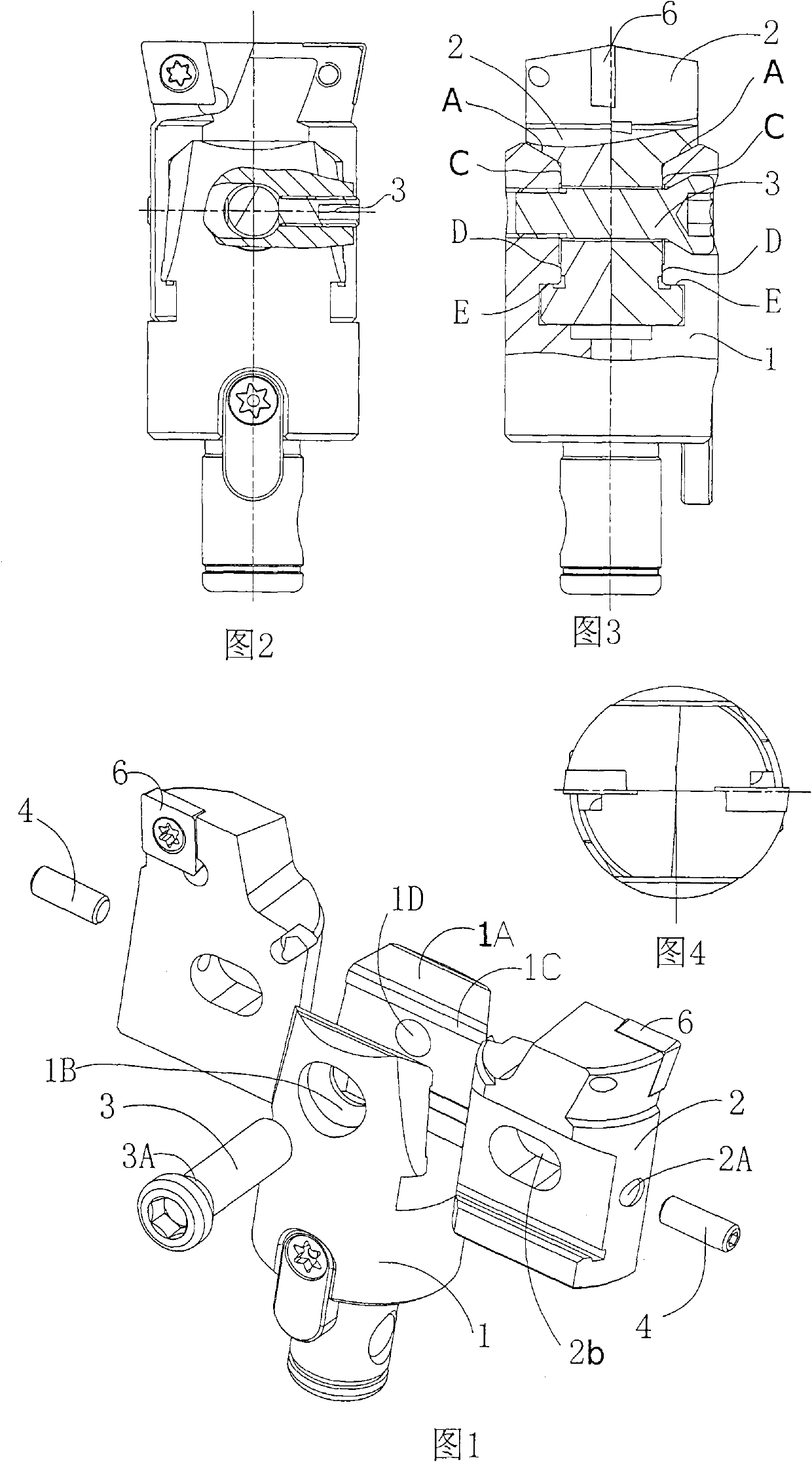
[0003] The above-mentioned structure still has some deficiencies in use; mainly: 1) the slope 1A on both sides of the T-shaped groove is a mating surface (cooperating with the A surface of the blade holder); and the upper section surface 1C of the parallel groove wall plane (The part between the top of the T-shaped slot and the locking screw) is a non-fitting surface with a large gap (generally 0.5-1.0mm); the blade seat will produce a slight deflection (random swing) during use, resulting in two blade seats 2 There is a height difference S within about 0.1mm between the blades 6 (such as Figure 10 to Figure 11 shown); in this case, the cutting force will be unbalanced when cutting with double-edged equal height. There is a gap in the inner hole of the body, and the adjusting screw is pressed against the locking screw; when the blade seat on one side is adjusted, and then the blade seat on the other side is adjusted, the adjusting screw is easy to move slightly due to force. The adjusted insert seat will move accordingly (causing the cutting size to become larger), affecting the adjustment accuracy and causing inconvenience in use; although the gap can be made smaller, it will increase the processing cost

Method used


Image

  • Advanced rough boring head
  • Advanced rough boring head
  • Advanced rough boring head

Examples


Embodiment Construction

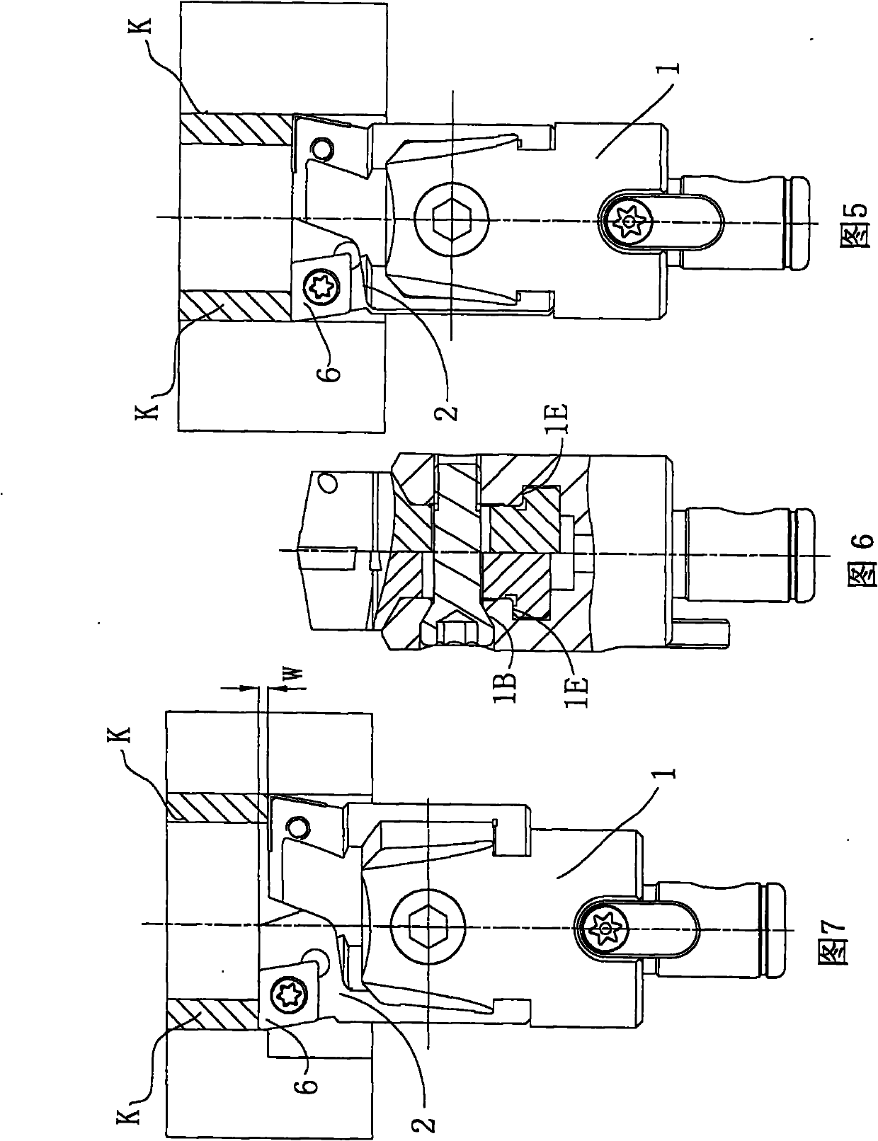
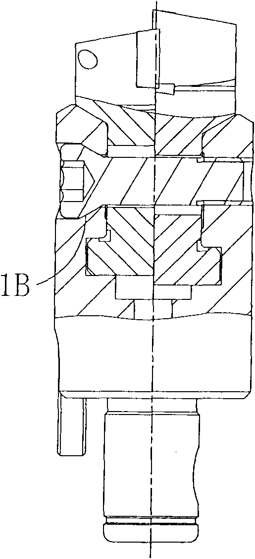
[0020] As shown in the figure: the present invention changes the original non-matching upper surface 1C between the main body 1 and the blade seat 2 into a very small clearance matching surface, preferably the clearance is within 0.05mm; this can effectively ensure two blades The tip height error is less than 0.03mm, which meets the requirements of double-edged cutting with equal height. The mating surface can be made into a very small clearance matching surface or a small interference matching surface; for example, the body and the insert seat can be made approximately For an interference of 0.005-0.01mm, the width of the interference surface is the same as that of the T-slot, and the length is about 1mm or less. Because the T-slot structure made on the upper part of the main body 1 has certain elasticity, the slider can still move under the condition of slight interference; in this way, when the locking screw is locked, the contact surface of the interference surface is positi...


PUM


Abstract

The invention relates to a rough boring head, aiming to provide a rough boring head with the characteristics of convenient adjustment, high precision and long service life. The technical scheme of the invention is as follows: the advanced rough boring head comprises a body, a blade bearing, a locking screw, an adjusting screw and a blade, wherein the top end of the body is provided with a T-shaped groove; two blade bearings are embedded in the T-shaped groove after being arranged in a reverse symmetry manner; the locking screw crosses the column hole of a groove wall at one side of the T-shaped groove transversely and elongated slots in the two blade bearings, and then screws into the screw hole of a groove wall at the other side of the T-shaped groove to fix the two blade bearings on the body; the two blade bearings are respectively provided with a screwed hole aligning with the elongated slots, and the screwed hole is internally provided with an adjusting screw; and the distance between the upper section of the inner side groove wall of the T-shaped groove and the surfaces of the blade bearings is within -0.01-0.05mm. The transition position of the screw head of the locking screw and the screw are manufactured into a conical surface, and the position corresponding to the column hole of the groove wall of the T-shaped groove of the body is manufactured into a conical hole matched with the conical surface.

Description

Technical field [0001] The invention relates to a metal processing tool, especially a rough boring head. Background technique [0002] Boring tool (boring head) is a commonly used tool in the metal processing industry, mainly used for processing large-size round holes or inner cavity surfaces. The conventional boring tool structure is mainly composed of body 1, blade seat 2, locking screw 3, adjusting screw 4, blade 6 and other parts ( Figure 9-11 Shown); a T-slot is made at the top of the body 1, two insert holders 2 are arranged in reverse symmetrical relation to each other and then embedded in the T-slot, the locking screw 4 crosses the T-slot and two insert holders 2 transversely After the long slot 2b in the middle, fix the two blade holders 2 on the main body 1. The two blade holders 2 are also respectively formed with a screw hole aligned with the long slot, and the screw hole locates an adjusting screw; rotate the adjusting screw Pressing the top end of the locking screw...

Claims


Application Information

Patent Timeline
Patent Type & Authority Applications(China)
IPC IPC(8): B23B27/00B23B29/03
Inventor 廖进堃
Owner JIAXING YONGJIA PRECISION MASCH MFG CO LTD
Why Eureka
Eureka Blog
Learn More