
Suction nozzle with soft cavity throttling bodies inside

A technology for throttling fluids and cavities, applied in road cleaning, construction, cleaning methods, etc., can solve the problems of poor passability, large particles of garbage can not reach the suspension speed, and the air dispersion speed is low, and achieves significant energy saving and reduced speed. The effect of reducing energy consumption, throttling and energy consumption

Inactive Publication Date: 2010-07-07
徐国栋
View PDF2 Cites 8 Cited by
  • Summary
  • Abstract
  • Description
  • Claims
  • Application Information

AI Technical Summary

Problems solved by technology

[0002] The suction nozzle of the existing road sweeper and road washing vehicle has a suction nozzle and a circulating air flow blowback port. The cross-sectional area of ​​the passage where the garbage muddy water moves with the air flow is relatively large, the air flow dispersion speed is low, and the large particles of garbage cannot reach the suspension speed, so they cannot be reliably Pneumatically pull it off the ground and transport it to the garbage bin. If the height of the nozzle cover is lowered from the road, large pieces of garbage cannot enter the nozzle; when there are bumps on the road, the passability is not good. The existing patent number is 200610103436.8 A suction nozzle of a road sweeper; Patent No. 200710044141.3 A pure suction type road sweeper suction nozzle is such a technical problem

Method used


Image

  • Suction nozzle with soft cavity throttling bodies inside
  • Suction nozzle with soft cavity throttling bodies inside
  • Suction nozzle with soft cavity throttling bodies inside

Examples


Embodiment Construction

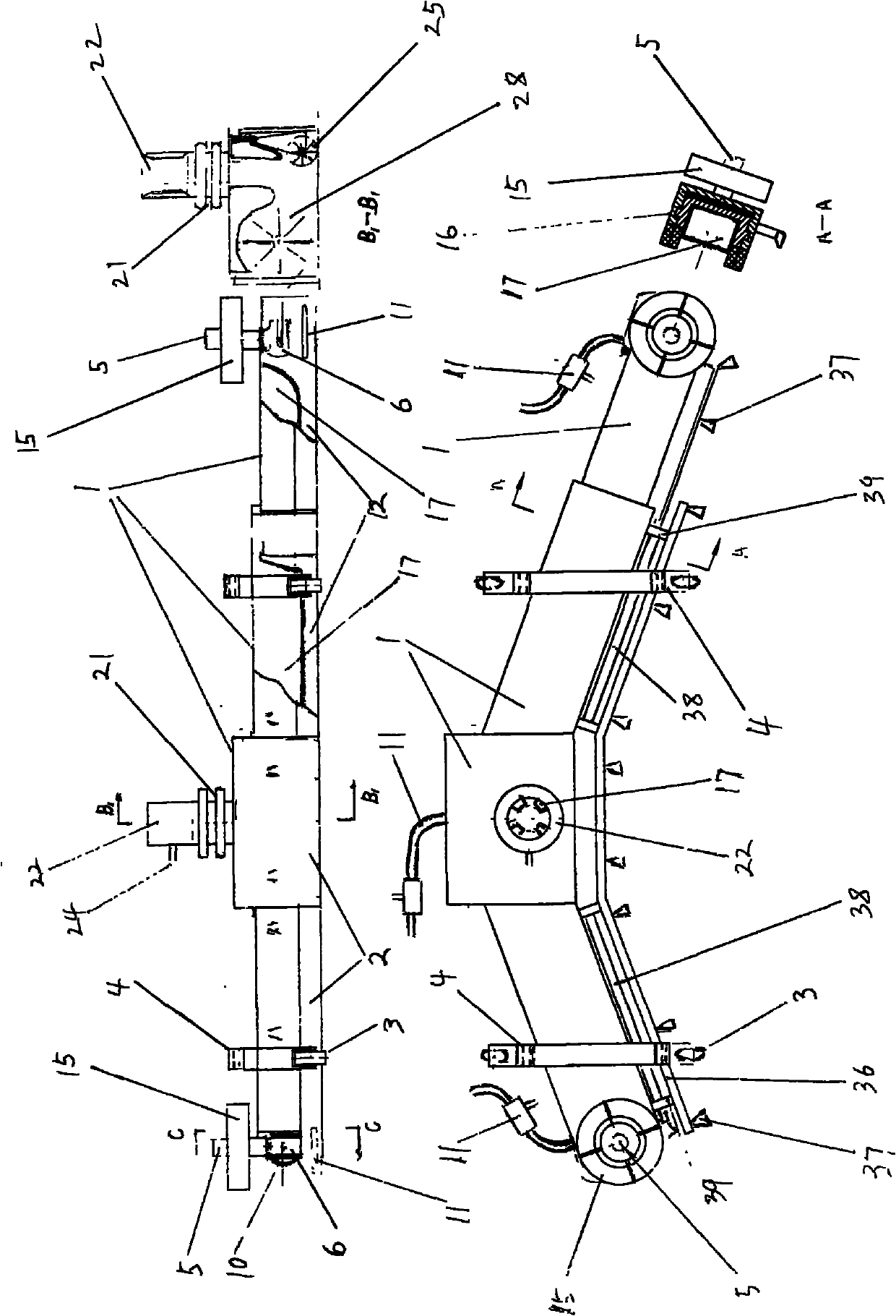
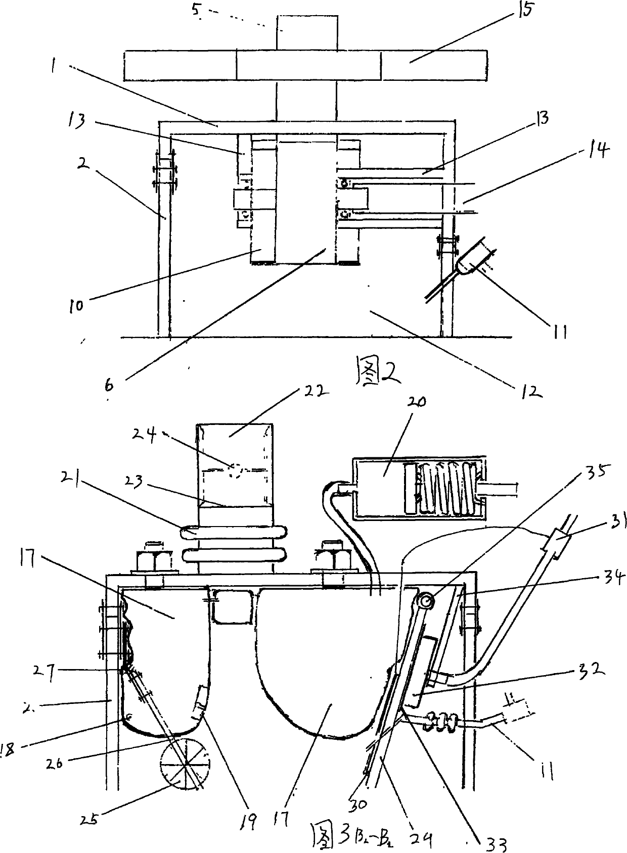
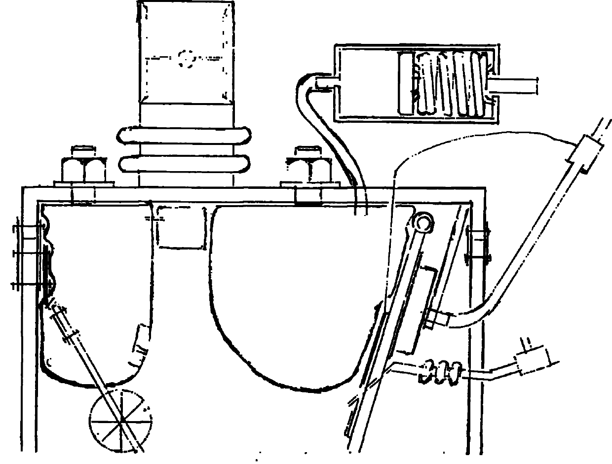
[0015] Below in conjunction with accompanying drawing, the specific mode of the suction nozzle with soft cavity throttling body is described in detail, as figure 1 , figure 2 , image 3 The suction nozzle is the main part of the suction nozzle in the middle section. The suction nozzles on the left and right sides are on both sides of the suction nozzle in the middle section. After telescopic sliding to 16, it is inclined forward and protrudes to the outside of the car body. The front and rear sealing rubber skirts 2, the airflow amplifier 22 supporting the walking wheels 3 and the annular nozzle in the middle area are connected to the upper cover 1 through the corrugated middle suction pipe 21, and the suction nozzles on the left and right sides have sealants on the front, rear and outer end faces of the upper cover 1 The left and right anti-collision guide wheels 15 fixed on the upper end of the skirt 2 and the outermost end upper cover 1 . The left, middle and right three...


PUM


Abstract

The invention provides a suction nozzle for cleaning the road surface, which relates to the field of a road sweeper component. The suction nozzle mainly solves the following problem: under the condition that the air quantity of a blower of a road sweeper is not changed, more than one closed cavity bodies made of soft materials are additionally arranged between an upper cover in the suction nozzle and the road surface so as to exert the function of throttling and press air flow of an air flow channel in the suction nozzle to cling to the road surface for rapid flowing, thereby sucking garbage into a garbage can. Each independently closed soft cavity throttling body is provided with a vent pipe which is connected to a space with the pressure intensity being equal to or higher than that of the air flow at the lower part or is connected with a pressure balancer. The suction nozzle further comprises the upper cover, a peripheral sealant skirt, a framework, supporting road wheels, a traction mechanism, a left air suction pipe orifice, a middle air suction pipe orifice and a right air suction pipe orifice, wherein the left and right air suction pipe orifices move along with a left suction nozzle or a right suction nozzle to extend out of a sweeper body for operation, and can retract to the left and right sides in a middle suction nozzle; each air suction pipe orifice is provided with a large-caliber air flow amplifier, an air back-blowing knife connected with a small-caliber air flow amplifier is respectively arranged at the lower rear part of each air suction pipe orifice, and each air back-blowing knife is matched with the blowing and sucking air flow of the blower on the road sweeper to blow and suck the garbage into the garbage can of the road sweeper.

Description

technical field [0001] The invention relates to a suction nozzle for cleaning road surfaces, which relates to the field of road washing and sweeping vehicle components. Background technique [0002] The suction nozzle of the existing road sweeper and road washing vehicle has a suction nozzle and a circulating air flow blowback port. The cross-sectional area of ​​the passage where the garbage muddy water moves with the air flow is relatively large, the air flow dispersion speed is low, and the large particles of garbage cannot reach the suspension speed, so they cannot be reliably Pneumatically pull it off the ground and transport it to the garbage bin. If the height of the nozzle cover is lowered from the road, large pieces of garbage cannot enter the nozzle; when there are bumps on the road, the passability is not good. The existing patent number is 200610103436.8 A road sweeper suction nozzle; Patent No. 200710044141.3 A pure suction type road sweeper suction nozzle is suc...

Claims


Application Information

Patent Timeline
Patent Type & Authority Applications(China)
IPC IPC(8): E01H1/08
Inventor 徐国栋徐江钥李鑫徐峰
Owner 徐国栋
Learn More