
Integrated light source measuring apparatus

A technology of measuring device and light source, applied in the direction of measuring device, optical radiation measurement, device with multiple detectors, etc., can solve the problems of shortening, decreased sensitivity, easy wear life of camera shutter, etc. Effect

Inactive Publication Date: 2010-07-07
DAE HAN ULTRAVISION
View PDF5 Cites 2 Cited by
  • Summary
  • Abstract
  • Description
  • Claims
  • Application Information

AI Technical Summary

Problems solved by technology

[0005] However, there are many problems with the measurement device using the optical camera of the prior art, and there are many problems in the implementation of the technique of correcting the gray scale of the measurement light source
[0006] That is, using the existing optical camera measurement device, a CCD (charge-coupled device) is used to photograph and judge the luminosity of an LED module integrated with a plurality of LED (light-emitting diode) light sources from the front. The flatness of the camera lens or the balance of the radius of curvature (R) of the camera lens will produce optical errors that are edge phenomena
In addition, when the same product is used repeatedly, there is a problem that the sensitivity of the CCD decreases and the measurement error increases
Not only that, each LED module will shorten the life of the camera shutter due to easy wear and tear when the camera performs 12 shots

Method used


Image

  • Integrated light source measuring apparatus
  • Integrated light source measuring apparatus
  • Integrated light source measuring apparatus

Examples


Embodiment Construction

[0025] Preferred embodiments of the present invention will be described in detail below with reference to the accompanying drawings. It should be pointed out that the interpretation of terms or words in this specification and claims is not limited to the common understanding and the meaning in the dictionary. A principle that should be explained is that the inventor can properly define For the concepts of terms, their explanations should adopt the meanings and concepts consistent with the technical status of the present invention. Therefore, it should be understood that the embodiments described in this specification and the structures shown in the drawings are only preferred embodiments of the present invention, not all technical ideas of the present invention, which may also be the corresponding equivalents and modified examples of the present application .

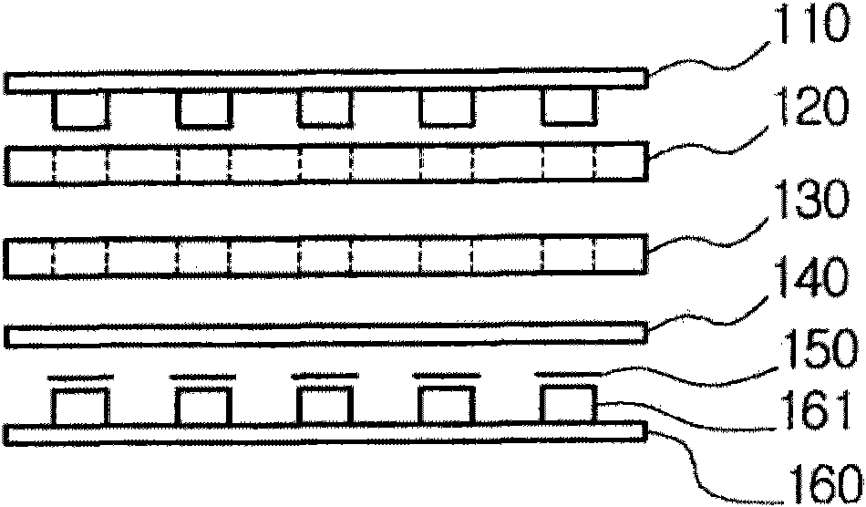
[0026] figure 1 is a cross-sectional view of the integrated light source measurement system according to the embodi...


PUM


Abstract

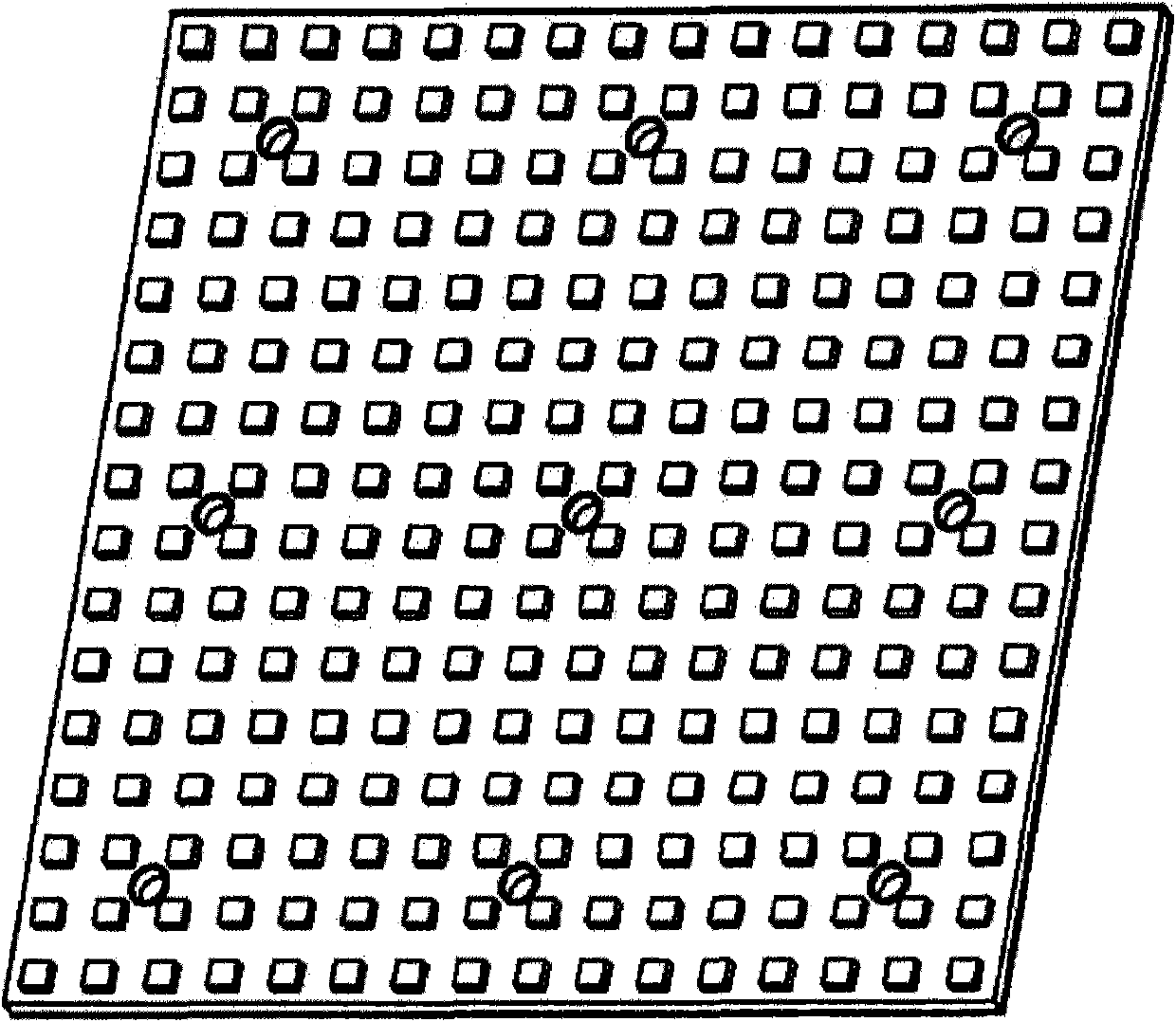
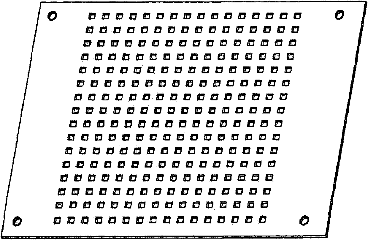
The present invention provides an integrated light source measuring apparatus capable of measuring luminosity rapidly and preventing generation of edge phenomenon in the measuring process of integrated light source. The integrated light source measuring apparatus comprises a clathrate lightproof board, through holes having identical shape and number with LEDs are located on the same positons of the LEDs in an LED module on the clathrate lightproof board, lateral walls of each LED are surrounded by the through holes, the integrated light source measuring apparatus also comprises a light conducting plate having through holes with identical number with that of the through holes of the clathrate lightproof board are located at the same positioned of the through holes for preventing lights generated by each LED and passing through the clathrate lightproof board from leaking from side faces in advancing process, a light splitting filter reducing the greyscale of lights generated by each LED, an infrared ray cutting-off filter for cutting off the infrared ray contained in the lights from the light splitting and a sensor module having a plurality of photo-sensors arranged at positions corresponding to that of the LEDs.

Description

technical field [0001] The invention relates to a light source measuring device, in particular to an integrated light source measuring device capable of measuring the grayscale and chromaticity of multiple light sources. Background technique [0002] At present, there are many kinds of light sources such as filament light sources (electric lamps), gas-filled light sources (fluorescent lamps), and semiconductor light sources (LEDs). When manufacturing companies manufacture a large number of light sources, the products of each unit will inevitably have deviations in grayscale and chromaticity. [0003] In order to reduce this deviation, each manufacturing company classifies and measures products according to multi-level grayscale and chromaticity deviation, thereby separating them. [0004] In this case, with the current technical level, on average, if it is class 1, there will be a deviation of about 10-30%, which can be recognized by the naked eye in the case of integrated l...

Claims


Application Information

Patent Timeline
Patent Type & Authority Applications(China)
IPC IPC(8): G01M11/02
CPCG01J1/26G01J1/4228G01J1/44G01J2001/448G02B5/282
Inventor 金载乙
Owner DAE HAN ULTRAVISION
Learn More