
Double-field-of-view stereoimaging optical system based on integrated shared primary mirror

An optical system and stereoscopic imaging technology, applied in the field of aerospace optical remote sensors, can solve the problems of large satellite weight and volume, affecting imaging quality and surveying and mapping accuracy, and difficult to guarantee the stability and accuracy of the camera structure, achieving good structural stability and volume Reduced, easy on-orbit detection effects

Inactive Publication Date: 2011-03-30
BEIJING RES INST OF SPATIAL MECHANICAL & ELECTRICAL TECH
View PDF0 Cites 0 Cited by
  • Summary
  • Abstract
  • Description
  • Claims
  • Application Information

AI Technical Summary

Problems solved by technology

[0004] Judging from the current research status at home and abroad, the existing traditional aerospace surveying and mapping cameras usually use two or three sets of cameras for stereoscopic surveying and mapping, that is, two or three cameras with different fields of view are respectively installed on an optical substrate. Realize three-dimensional mapping (such as Japan's ALOS / Prism), which not only causes the weight and volume of the satellite to be too large, but also makes it difficult to guarantee the structural stability and accuracy of each camera. Each independent optical system is subjected to thermal loads. When deformation occurs, there will be changes in the optical axis and different changes in the internal orientation elements, which will ultimately affect the imaging quality and mapping accuracy
Therefore, in the further development of this three-dimensional surveying and mapping system using a discrete optical-mechanical structure, it will face more and more difficulties.

Method used


Image

  • Double-field-of-view stereoimaging optical system based on integrated shared primary mirror
  • Double-field-of-view stereoimaging optical system based on integrated shared primary mirror
  • Double-field-of-view stereoimaging optical system based on integrated shared primary mirror

Examples


Embodiment Construction

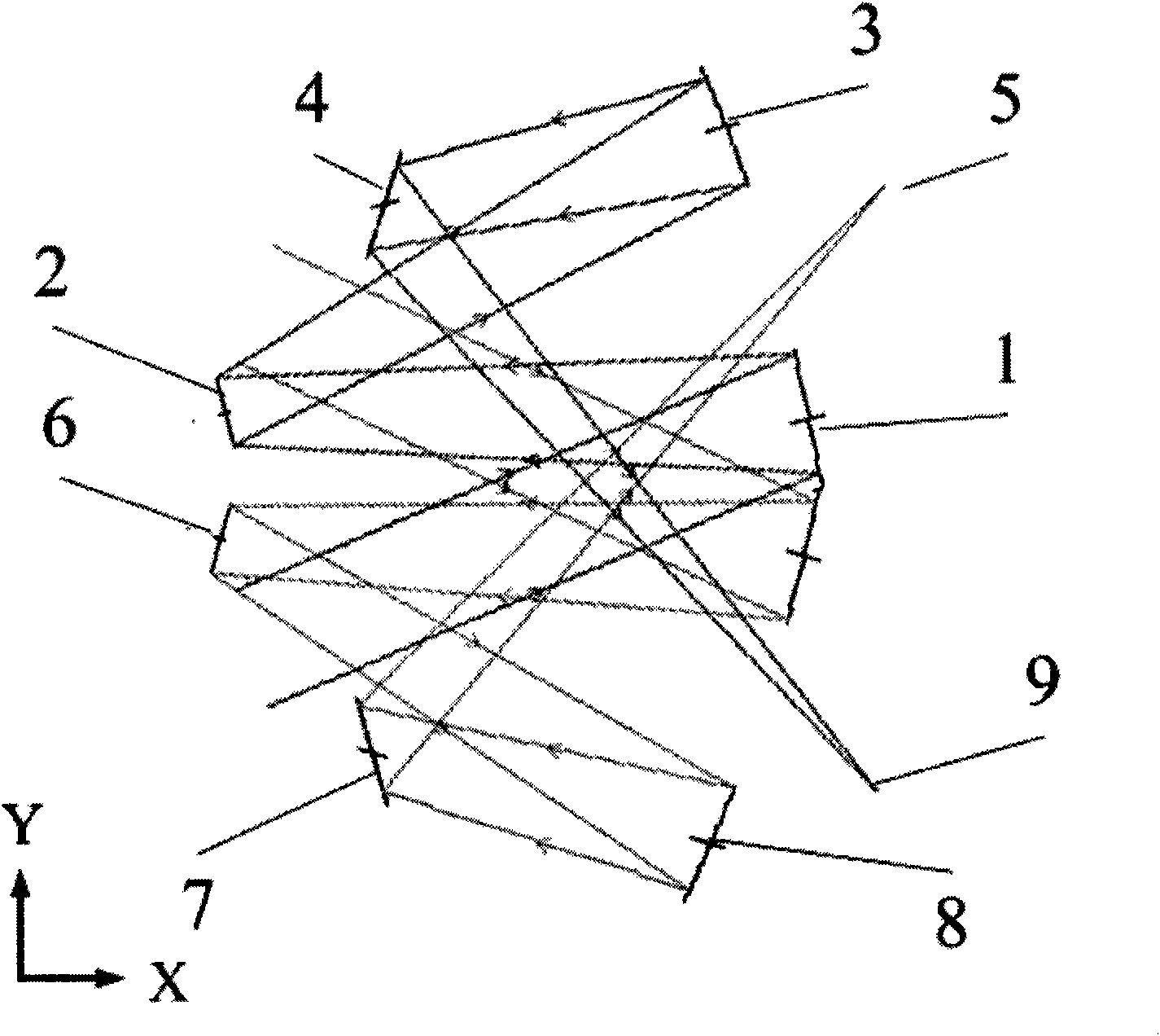
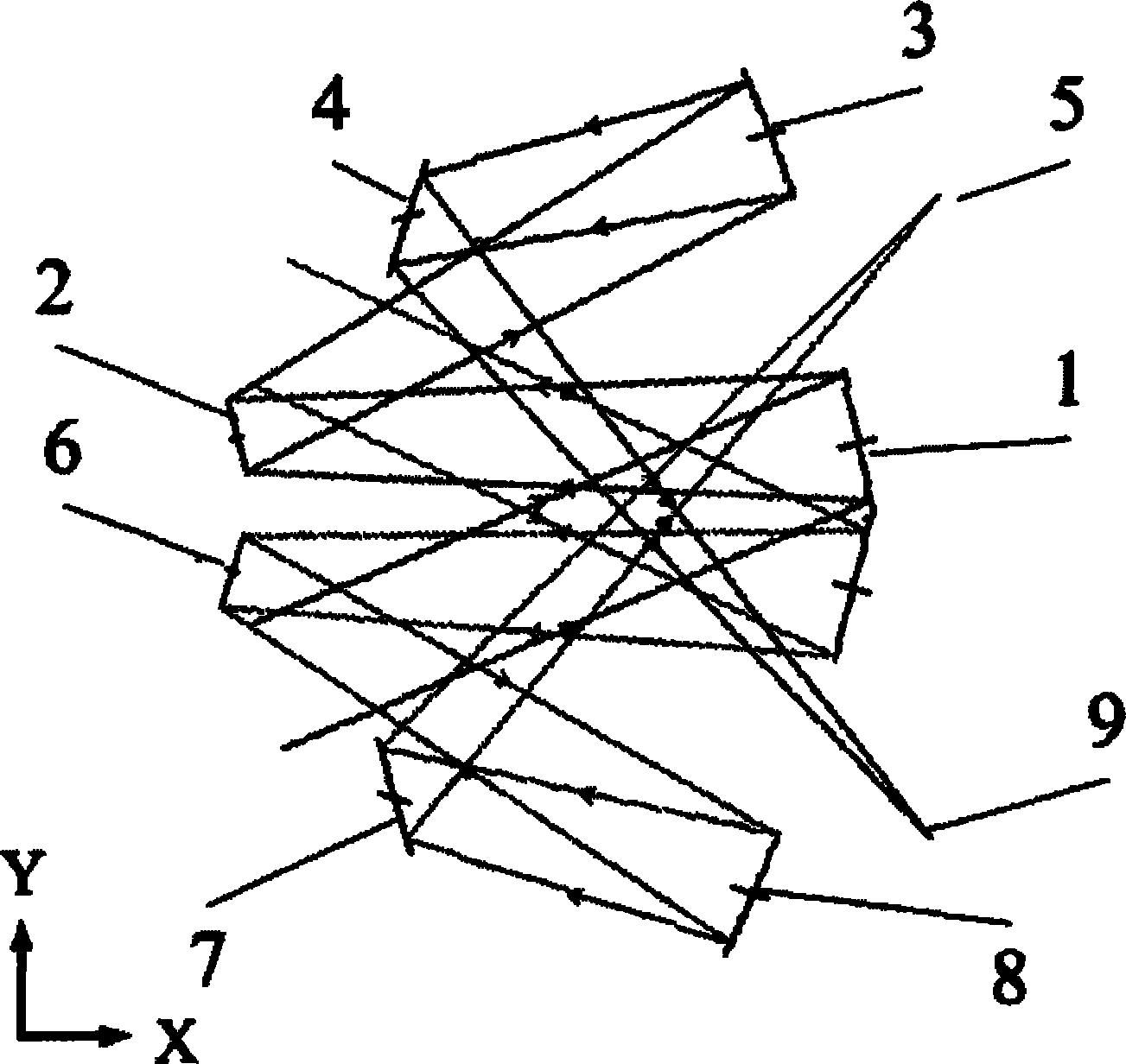
[0014] Such as figure 1 Shown, the structural principle diagram of the system of the present invention. The system includes a welded primary mirror 1, two secondary mirrors 2, 6, two triple mirrors 3, 8, two plane folding mirrors 4, 7, and two receiving image surfaces 5, 9, and the welded primary mirror 1 consists of two The block mirrors are welded into a ">" structure, welding the main mirror 1, the second secondary mirror 6, the second three mirrors 8, the second plane folding mirror 7, and the second receiving image surface 5 to form a front-view system. The primary mirror 1, the first secondary mirror 2, the first third mirror 3, the first plane folding mirror 4, and the first receiving image surface 9 constitute a rearview system. The central axis of the first secondary mirror 2 is the main optical axis of the rear-view optical system, and the central axis of the second secondary mirror 6 is the main optical axis of the forward-view optical system.

[0015] The first p...


PUM


Abstract

The invention provides a double-field-of-view stereoimaging optical system based on an integrated shared primary mirror, which consists of a two three-reflector abaxial optical systems and comprises a welding primary mirror, two secondary mirrors, three third mirrors, two plane deflection mirrors and two receiving surfaces. Through using two beams of symmetrical deviated field-of-view incident light rays, stereopairs are formed through the optical systems, and the invention can be used for realizing the spatial stereometric mapping with large base-height ratio and high precision. The system of the invention welds the two main mirrors of the two optical systems at a certain angle for realizing the integration of the optical systems, and the stability of the included angle between the frontfield of view and the back field of view is ensured, so the stability of the base-height (B / H) ratio is ensured, in addition, the welding angle can be changed, and the required base-height (B / H) ratio can be flexibly realized. The system of the invention has the advantages of light weight, small size and high thermal stability, so the high stability of inner orientation elements can be obtained, and the high-precision correction on the images is realized.

Description

technical field [0001] The invention belongs to the technical field of aerospace optical remote sensors, and relates to a dual-field stereo surveying and mapping optical system. Background technique [0002] Due to the rapid development of aerospace optical remote sensor technology, the requirements for the application level of remote sensor systems continue to increase. [0003] Surveying and mapping satellites use satellites, spacecraft or space stations as platforms, carry imaging remote sensors that meet the requirements of stereo photography, take pictures of the earth's surface, obtain image information, and accurately measure the topography and features (targets) of the earth's surface through photogrammetry processing. Shape, size, and spatial location to generate a variety of surveying and mapping assurance products required for terrestrial applications. [0004] Judging from the current research status at home and abroad, the existing traditional aerospace surveyi...

Claims


Application Information

Patent Timeline
Patent Type & Authority Patents(China)
IPC IPC(8): G03B35/00G02B27/22G01S17/89
Inventor 傅丹鹰黄颖姚罡王建永李博李瀛搏
Owner BEIJING RES INST OF SPATIAL MECHANICAL & ELECTRICAL TECH
Learn More