
Light-emitting module with high heat conduction and light guide functions and devices applying same

A technology for light-emitting modules and light-emitting devices, which can be applied to identification devices, semiconductor devices, instruments, etc., can solve problems such as inconvenience and lack, and achieve the effects of reducing costs, improving yield, and improving stability.

Inactive Publication Date: 2010-07-07
HARVATEK CORPORATION
View PDF0 Cites 0 Cited by
  • Summary
  • Abstract
  • Description
  • Claims
  • Application Information

AI Technical Summary

Problems solved by technology

[0005] Therefore, it can be seen from the above that the current packaging structure of light-emitting modules and light-emitting diode components obviously has inconvenience and shortcomings, and needs to be improved.

Method used


Image

  • Light-emitting module with high heat conduction and light guide functions and devices applying same
  • Light-emitting module with high heat conduction and light guide functions and devices applying same
  • Light-emitting module with high heat conduction and light guide functions and devices applying same

Examples


Embodiment Construction

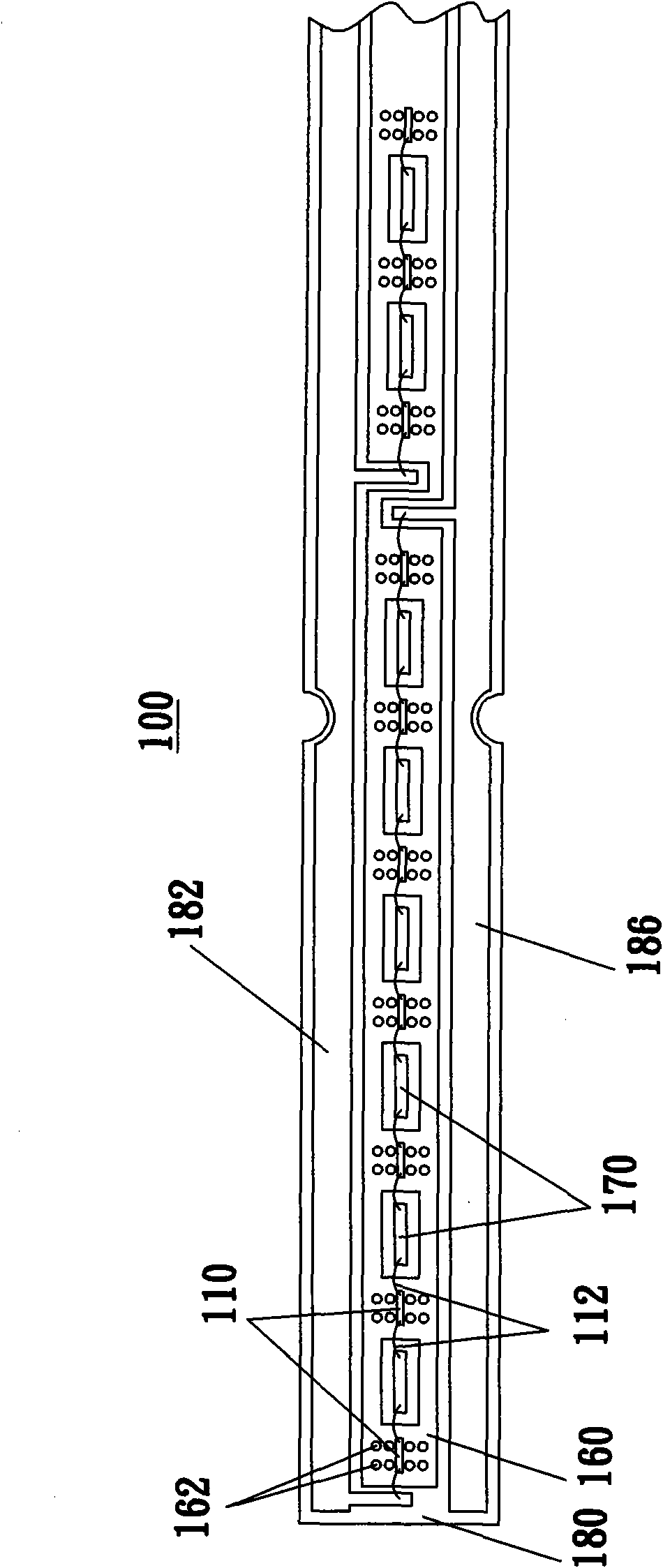
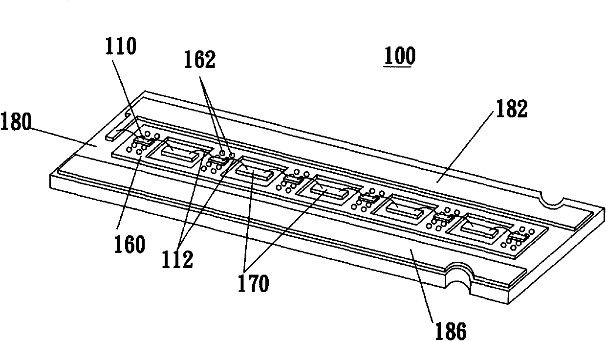
[0035] Please also refer to Figure 1 to Figure 5 , which respectively show different views of the first embodiment of the lighting module 100 of the present invention. The light emitting module includes a plurality of light emitting chips 110 and a conductive substrate. The conductive substrate includes a base material 180 , a chip pad 160 , a wire pad 170 and a heat conduction layer 150 .

[0036] The base material 180 is formed with a first surface (i.e. figure 1 the front side shown in , not labeled) and the second side opposite the first side (i.e. figure 2 The back side shown in , not labeled), is provided with conductive traces 182, 186 on the first side. Wherein the conductive track 182 is a positive conductive track, and the conductive track 186 is a negative conductive track. Of course, the positive and negative poles of the above-mentioned conductive traces can be adjusted as required, or combined with the chip pad 160 to meet the restrictions of different typ...


PUM


Abstract

The invention provides a light-emitting module, comprising a substrate, a plurality of light-emitting chips arranged on the substrate and fluorescent adhesive layers and protective adhesive layers covering the light-emitting chips, the substrate comprises a base material and chip pads which are arranged on the base material and are used for bearing the light-emitting chips; a plurality of holes are formed by penetrating through the chip pads and the base material; and the fluorescent adhesive layers and the protective adhesive layers comprise light guide structures so as to guide the light-emitting chips to emit light. The substrate structure of the light-emitting module realizes heat and electricity separation and improves the heat dissipation effects of the light-emitting chips. Meanwhile, while working, the light-emitting module can improve the stability of the colors and the capability of processing the light shapes.

Description

【Technical field】 [0001] The invention relates to a packaging structure based on multiple light-emitting diode chips, in particular to a light-emitting module with high heat conduction and light conduction functions and its application device. 【Background technique】 [0002] See Figure 12 , which shows a schematic structural view of a conventional lighting module 10 . The light emitting module 10 includes a light emitting diode component (LED Component) 11 , copper foil 12 , insulating and thermally conductive glue 14 and an aluminum plate 16 . The manufacturing process of the light emitting module 10 is complicated and the cost is high. In addition, the heat dissipation effect of the substrate composed of the copper foil 12 , the insulating heat-conducting adhesive 14 and the aluminum plate 16 needs to be improved. [0003] At present, the dispensing mode is widely used to package the light-emitting diode chip (LED Chip) on a metal support, and then the packaged light-em...

Claims


Application Information

Patent Timeline
Patent Type & Authority Applications(China)
IPC IPC(8): H01L25/13H01L33/50H01L33/58H01L33/62H01L33/64G09F9/33
CPCH01L24/97H01L2224/48091H01L2224/48227
Inventor 汪秉龙庄峰辉吴文逵
Owner HARVATEK CORPORATION
Learn More