Eureka AIR delivers breakthrough ideas for toughest innovation challenges, trusted by R&D personnel around the world.

Low-voltage double-power supply loop device and control method thereof

A technology of power supply device and dual power supply, which is applied in the direction of circuit device, emergency power supply arrangement, electrical components, etc., which can solve problems such as short power supply time, inability to supply sufficient power supply, power supply and backup power supply can not start power supply at the same time, to avoid failure damage effect

Inactive Publication Date: 2010-07-07
MOXA INC
View PDF0 Cites 8 Cited by
  • Summary
  • Abstract
  • Description
  • Claims
  • Application Information

AI Technical Summary

Problems solved by technology

[0004] (1) The uninterruptible power system contains a charger and a rechargeable battery pack inside, and the components such as the charger and the rechargeable battery pack cannot withstand high temperatures, so they cannot provide power for electronic system equipment in a high temperature environment
[0005] (2) The main power supply and the backup power supply of the uninterruptible power system cannot start power supply at the same time, and only the main power supply or the backup power supply can be selected. When the electronic system equipment is under heavy load, it cannot provide enough power for the electronic system equipment
[0006] (3) The backup power supply of the uninterruptible power system is to charge the rechargeable battery pack by the charger through the mains. When there is no power failure without warning, the rechargeable battery pack is used to supply power, but the rechargeable battery can only provide short-term power supply Therefore, it is impossible to supply sufficient power for electronic system equipment, and it is still necessary to wait for the recovery of mains power supply

Method used


Image

  • Low-voltage double-power supply loop device and control method thereof
  • Low-voltage double-power supply loop device and control method thereof
  • Low-voltage double-power supply loop device and control method thereof

Examples


Embodiment Construction

[0019] In order to achieve the above-mentioned purpose and effect, the technical means and structure adopted by the present invention are now illustrated in detail with respect to preferred embodiments of the present invention. Its features and functions are as follows to facilitate a complete understanding.

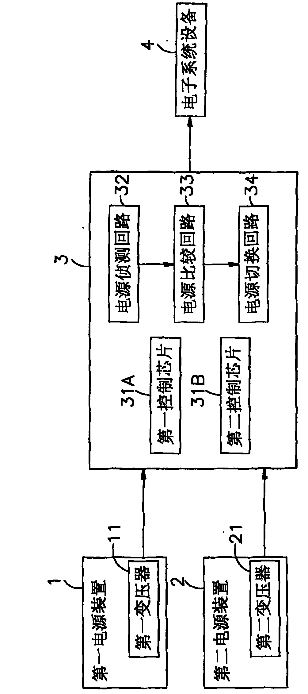
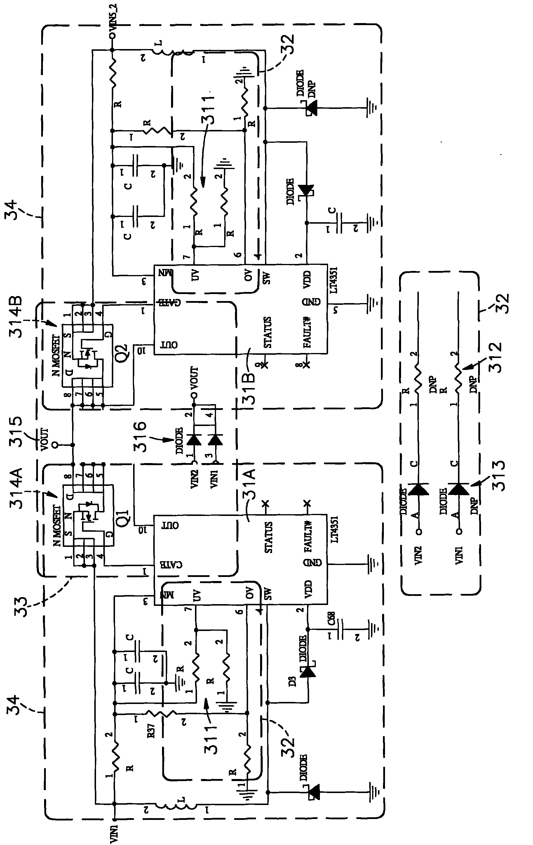
[0020] see figure 1 , figure 2 As shown, it is a circuit block diagram and a circuit diagram of a preferred embodiment of the present invention. It can be clearly seen from the figure that the low-voltage dual power supply circuit of the present invention is composed of the first power supply unit 1, the second power supply unit 2 and the dual power supply unit. The power supply control loop is composed of 3, of which:

[0021] The first power supply device 1 is capable of inputting AC mains power, and the first power supply device 1 is provided with a first transformer 11 for converting the AC mains power into a low-voltage direct current.

[0022] The second power ...


PUM


Abstract

The invention relates to a low-voltage double-power supply loop device and a control method thereof. The low-voltage double-power supply loop device comprises a first power supply device, a second power supply device and a double-power supply control loop, wherein the first power supply device and the second power supply device are respectively input to the double-power supply control loop; the double-power supply control loop is provided with a first control chip and a second control chip; the first control chip and the second control chip are respectively connected with a power supply detection loop, a power supply comparison loop and a power supply switching loop; the first control chip and the second control chip detect the priorities of the first power supply device and the second power supply device through the power supply detection loop; and when a first prior power supply device has power failure, the voltage is compared through the power supply comparison loop, the first prior power supply device is switched to the second prior stand-by power supply device by the power supply switching circuit, a stand-by power supply continuously supplies the power to an external electronic device, the loss of important data in the external electronic device is prevented, and the loss with lots of money is avoided.

Description

technical field [0001] The present invention relates to a low-voltage dual power supply circuit device and its control method, especially to use the dual power supply control circuit to detect the priority of the first power supply device and the second power supply device. When a power failure occurs, the voltage can be compared , switch the first-priority power supply unit to the second-priority backup power supply unit, and be powered by the backup power supply. Background technique [0002] With the advancement of electronic technology, people rely more and more on power sources, so power outages without warning will cause losses to all walks of life, especially major electronic technology companies are equipped with a large number of high-priced electronic devices. System equipment, so it will cause an inestimable large amount of loss, and for electronic system equipment (such as desktop computers, barebone systems, servers and network storage devices, etc.), if the dat...

Claims


Application Information

Patent Timeline
Patent Type & Authority Applications(China)
IPC IPC(8): H02J9/00H02J9/06
Inventor 张宽雄
Owner MOXA INC
Why Eureka
Eureka Blog
Learn More