Noise reduction structure of motor of vacuum cleaner
A vacuum cleaner and noise reduction technology, which is applied in the direction of vacuum cleaners, electrical components, electromechanical devices, etc., can solve the problems of limited noise reduction structure noise reduction effect, reduction of noise energy, and inability to achieve sound insulation or noise reduction effects, etc., to achieve good noise reduction effect , reduce noise energy, good sound insulation and noise reduction effect
- Summary
- Abstract
- Description
- Claims
- Application Information
AI Technical Summary
Problems solved by technology
Method used
Image

Examples
Embodiment 1
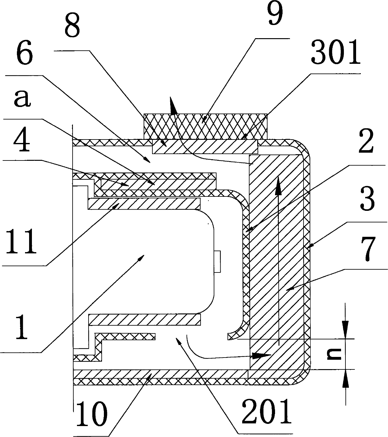
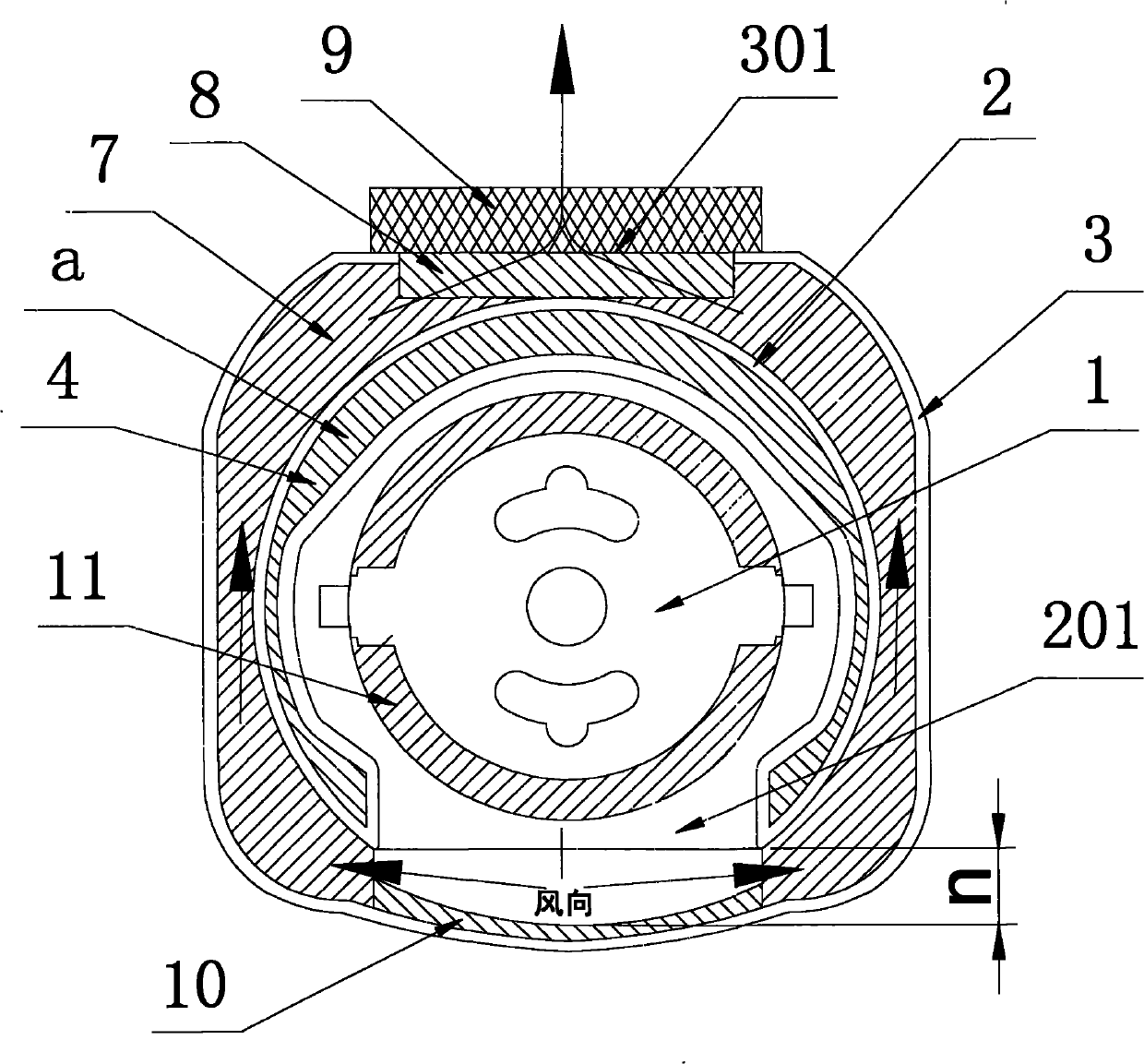
[0027] Example 1: First combine figure 1 , figure 2 As shown, the vacuum cleaner motor noise reduction structure provided by this embodiment includes a motor inner cover 2 and a motor outer cover 3 surrounding the motor 1, and the motor inner cover 2 is provided with a first air outlet 201 communicating with the motor 1, The motor cover 3 is provided with a second air outlet 301 , and the first air outlet 201 communicates with the second air outlet 301 through the air duct 6 formed inside the motor and between the outer covers 2 and 3 . The air duct 6 is provided with an outer cover sound-absorbing sponge 7 , the second air outlet 301 is filled with an air outlet sponge 8 , and an air outlet seamask 9 is provided outside the second air outlet 301 .
[0028] The motor inner cover 2 described in this embodiment is a double-layer hollow structure in view of its cross section, that is, this motor inner cover 2 has an additional circle of sound-absorbing cavity a on its original ...
Embodiment 2
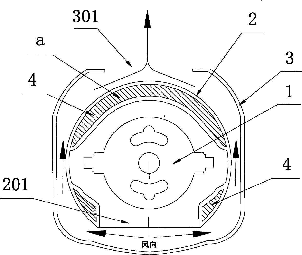
[0031] Embodiment 2: The difference from Embodiment 1 is that part of the motor inner cover 2 is a double-layer hollow structure. For details, see image 3 , the motor inner cover 2 in this embodiment has three additional sound-absorbing cavities a on its original outer wall, one of which is located at the upper position of the original outer wall of the motor inner cover 2, and the other two are located in the motor inner cover 2. The lower positions on the left and right sides of the original outer wall, and these three sound-absorbing chambers a are all open chambers, and their insides are all filled with inner cover sound-absorbing sponge 4 (not shown in the figure). The rest of this embodiment are the same as embodiment 1.
Embodiment 3
[0032] Embodiment 3: The difference from Embodiment 2 is that a sound-absorbing chamber a above the motor inner cover 2 is further divided into four chambers by three transverse partitions 5, and two chambers at the lower left and right sides of the motor inner cover 2 a, so the motor inner cover 2 of the present embodiment actually adds six silencing chambers a on its original outer wall, specifically see Figure 4 , and each sound-absorbing cavity a is also an open cavity, and the inside is filled with inner cover sound-absorbing sponge 4 (not shown in the figure). The rest of this embodiment are the same as embodiment 2.
PUM
 Abstract
Description
Claims
Application Information
 - R&D
- Intellectual Property
- Life Sciences
- Materials
- Tech Scout
- Unparalleled Data Quality
- Higher Quality Content
- 60% Fewer Hallucinations
Browse by: Latest US Patents, China's latest patents, Technical Efficacy Thesaurus, Application Domain, Technology Topic, Popular Technical Reports.
© 2025 PatSnap. All rights reserved.Legal|Privacy policy|Modern Slavery Act Transparency Statement|Sitemap|About US| Contact US: help@patsnap.com