
Adjustable leveling guide rail and leveling method thereof

An adjustable, flat guide rail technology, applied in construction, building structure, construction material processing and other directions, can solve the problems of wasting materials, difficult to level, affecting construction, etc., to achieve convenient use and disassembly, and enhance the ease of operation. , to ensure the effect of construction quality

Inactive Publication Date: 2010-07-14
HAOHE ENG & CONSTR
View PDF1 Cites 29 Cited by
  • Summary
  • Abstract
  • Description
  • Claims
  • Application Information

AI Technical Summary

Problems solved by technology

The structure of the traditional leveling guide rail mainly has the following defects: (1) the positioning is inaccurate. The existing leveling guide rail is generally placed on the concrete base after positioning with theodolite first, so that the position is easily moved when pouring concrete like this, resulting in the absence of the guide rail. The same horizontal plane affects the quality of the project; (2) it is not easy to level, the existing leveling guide rail has only one positioning nut, if a certain bracket is found to be uneven during concrete construction, there is no way to adjust the level immediately; (3) waste of materials, the existing three After the inclined leg guide rail support is burned by electric welding after the concrete is solidified, the entire support is scrapped and cannot be used continuously. The cost is high, and there are burn marks on the concrete surface, which affects the appearance of the project.
But this structure has the following defects: (1) the crossbeam of this structure adopts hollow type crossbeam, although this structure is conducive to the convenience of handling, but the processing technology is more complicated, and because it is a hollow structure, when the length of the crossbeam is large, it is easy to appear The phenomenon of being light in the middle and heavy at both ends causes the middle part of the beam to sag, making it difficult to control the leveling effect, thereby affecting the levelness of the overall pouring of the ground; (2) The structure has nuts in the beam, which determines that the beam must have a certain thickness, if a solid beam is used, the weight will be too large, if a hollow beam is used, the process will be more complicated, and it is inconvenient to use and disassemble; (3) Since the screw is not designed to be fixed or positioned The flatness is not enough. When secondary leveling is required, because the screw rod is connected with the nut placed in the large hole, the adjusting nut under the beam, and the positioning piece are all screwed. When the nut or adjusting nut is rotated, the screw rod cannot be fixed or positioned. It will cause the screw and other parts to rotate accordingly, and the beam will move, resulting in inaccurate leveling, affecting the construction, and failing to achieve the ideal pouring level, that is, once installed, it cannot be leveled at any time during the construction process ; (4) When it is used for pouring concrete on the ground in a large area, it is prone to concrete leakage

Method used


Image

  • Adjustable leveling guide rail and leveling method thereof
  • Adjustable leveling guide rail and leveling method thereof
  • Adjustable leveling guide rail and leveling method thereof

Examples


Embodiment 1

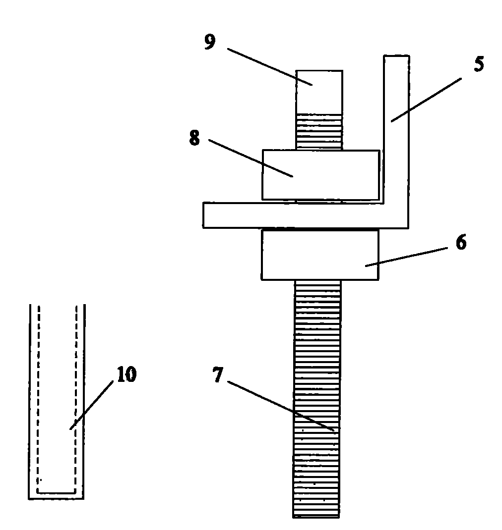
[0043] Figure 3 ~ Figure 4 shows the specific structure of this embodiment, such as image 3 As shown, the adjustable leveling guide rail includes a guide rail beam 5 and two supports, each support member includes a screw rod 7 and a nut, the screw rod 7 is connected with the guide rail beam 5 through a nut, and the end of the screw rod 7 is provided with Fixed block 9.

[0044] The fixed block 9 is integrally connected with the screw rod 7 and is an axial section at the upper end of the screw rod 7 . The fixing block 9 is hexagonal.

[0045] The supporting member also includes a locating member 10 , and the locating member 10 is matedly connected with the screw rod 7 . The positioning member 10 adopts an expansion bolt, and the lower section of the screw rod 7 is provided with threads, and the lower section of the screw rod is connected with the expansion bolt.

[0046] The section of the guide rail beam 5 is Shaped like Figure 5 (a) shown.

[0047] Such as image ...

Embodiment 2

[0059] This embodiment is the same as Embodiment 1 except for the following features: the adjustable leveling guide rail includes a guide rail beam and five supports, and the supports include positioning nuts, leveling nuts and screw rods, and the ends of the screw rods are provided with Fixed block. Such as Figure 7 As shown, the guide rail beam 5 is provided with five screw holes 11, and the screws pass through the screw holes and are connected with the guide rail beam through positioning nuts and leveling nuts.

[0060] The fixed block presents a quadrangular shape.

[0061] The positioning part adopts a screw sleeve.

Embodiment 3

[0063] This embodiment is the same as Embodiment 1 except the following features: the section of the guide rail beam is "]" or "I" shape, as shown in Figure (b) or Figure (c).

[0064] The fixing block is detachably connected to the screw rod, and the fixing block is engaged with the screw rod.


PUM


Abstract

The invention provides an adjustable leveling guide rail. The adjustable leveling guide rail comprises a guide rail beam and a plurality of supporting pieces, wherein each supporting piece comprises a screw rod and a nut; the screw rod is connected with the guide rail beam through the nut; the end part of the screw rod is provided with a fixing block which is hexagonal, tetragonal or triangular; the fixing block is connected with the screw rod in an integral molding mode or the fixing block is detachably connected with the screw rod; and the supporting piece also comprises a positioning piece connected with the screw rod in a fitting mode. The invention also provides a leveling method for realizing the leveling guide rail, namely, the levelness of the leveling guide rail is adjusted by rotating a leveling nut and a positioning nut. In a construction process, instant leveling is realized by clamping the fixing block, fixing the screw rod and adjusting the levelness of the guide rail by screwing the positioning nut and the adjusting nut respectively. The adjustable leveling guide rail has high leveling accuracy, can realize instant leveling in the construction process and has the advantages of low cost, convenient detachment, easy construction, clean environment, green construction and the like.

Description

technical field [0001] The invention relates to the technical field of building construction, in particular to an adjustable leveling guide rail and a leveling method thereof, which are mainly used for super-flat ground pouring and lattice construction of industrial workshops, and can improve the levelness of the overall ground pouring. Background technique [0002] Ultra-flat floor is currently the highest specification and standard floor construction technology in the world. It is designed to improve the flatness, wear resistance and prolong the service life of the ground, especially on the ground of logistics warehouses and precision industrial plants. It can bring great technical and economic benefits; this kind of ground can meet the requirements for the flatness and levelness of the ground for multi-storey storage shelves above 13m in height, equipment installation and full load, making the shelf 1. The equipment is easy to install and does not need to be adjusted repe...

Claims


Application Information

Patent Timeline
IPC IPC(8): E04G21/10
Inventor 周岳江创福仕召平朱向峰杨明
Owner HAOHE ENG & CONSTR
Learn More