Double-layer flame electric fireplace

An electric fireplace and flame technology, which is applied in the field of double-layer flame electric fireplace, can solve the problems of poor three-dimensional effect, small depth range, and few flame layers, etc., and achieve the effects of strong three-dimensional effect, large depth range, and improved simulation level

Inactive Publication Date: 2011-10-26
YIWU ANDONG ELECTRICAL APPLIANCES
View PDF1 Cites 0 Cited by
  • Summary
  • Abstract
  • Description
  • Claims
  • Application Information

AI Technical Summary

Problems solved by technology

[0003] The purpose of the present invention is to provide a double-layer flame with rich flame layers, large depth range and strong three-dimensional effect in order to solve the problems of the existing electric fireplace with few flame layers, small depth range and poor three-dimensional effect electric fireplace

Method used


Image

  • Double-layer flame electric fireplace
  • Double-layer flame electric fireplace
  • Double-layer flame electric fireplace

Examples


Embodiment 1

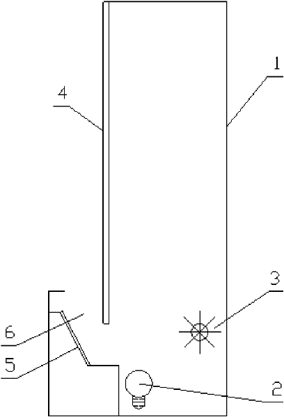
[0023] in such as figure 1 In the shown embodiment 1, a double-flame electric fireplace includes a housing 1, an imaging light source 2, a light processing device 3, and an imaging screen 4. The light from the imaging light source is irradiated to the back of the imaging screen of the electric fireplace through the light processing device On the surface, a reflective device 5 is also provided under the front side of the imaging screen. The reflective device is a reflective plate, and the reflective surface of the reflective plate is a fully reflective planar structure, forming an included angle with the height direction of the imaging screen as a whole. A light passage 6 is provided between the reflective device and the imaging screen, and the light from the imaging light source of the electric fireplace is irradiated onto the front surface of the imaging screen of the electric fireplace through the reflective device.

Embodiment 2

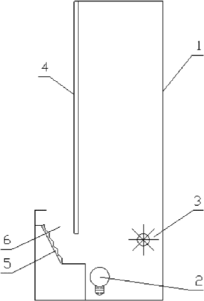
[0025] The reflective device of embodiment 2 is a reflector, and the reflective surface of the reflector is a curved surface structure with some concavo-convex surfaces (see figure 2 ), all the other are identical with embodiment 1.

Embodiment 3

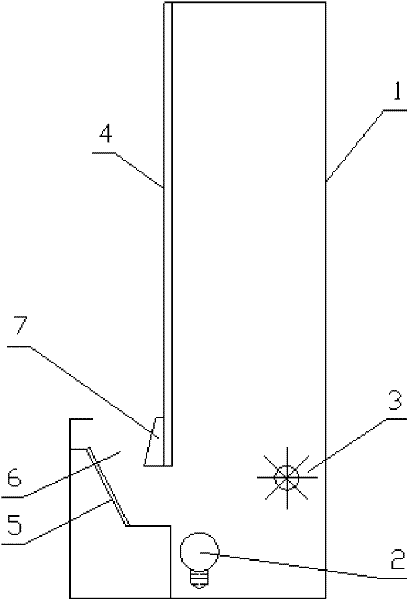
[0027] in such as image 3 In the shown embodiment 3, a simulated charcoal bed 7 is provided under the front side of the electric fireplace imaging screen, and a plurality of reflective structures 8 are provided on the front surface of the simulated charcoal bed, and the light channel 6 is arranged on the front side of the simulated charcoal bed , the light of the imaging light source of the electric fireplace is irradiated onto the reflective structure of the simulated carbon bed through the reflective device. The reflective structure is a reflective film, which is pasted on the surface of the simulated carbon bed (see Figure 8 ), the profile of the reflective film is polygonal, and the reflective area of ​​the reflective structure varies in size, between 0.1 and 0.5 square centimeters, and the reflective device is a partially reflective plane reflector, and all the other are the same as in embodiment 1.


PUM


Abstract

The invention discloses a double-layer flame electric fireplace. The double-layer flame electric fireplace comprises a case body, an imaging light source, a light processing unit and an imaging screen, wherein light of the imaging light source illuminates on the rear surface of the imaging screen of the electric fireplace through the light processing unit; a reflective device is arranged under the front side of the imaging screen; an optical channel is arranged between the reflective device and the imaging screen; and the light of the imaging light source illuminates on the front surface of the imaging screen of the electric fireplace through the reflective device. The double-layer flame electric fireplace effectively solves the problems of fewer layers, small depth range and poor three-dimensional effect of flame existing in the electric fireplace in the prior art. The double-layer flame electric fireplace has the advantages of abundant layers, large depth range and three-dimensionaleffect of stimulated flame, greatly improves the stimulating level of the electric fireplace, and has obvious economic benefits.

Description

technical field [0001] The invention relates to a simulated fireplace, in particular to a double-layer flame electric fireplace. Background technique [0002] Most of the electric fireplaces in the prior art have a single-layer flame structure mode, that is, the light from the imaging light source is processed by the light processing device and then irradiated on the rear surface of the electric fireplace imaging screen to simulate a flame pattern. The electric fireplace with this structure simulates The flame is a single-layer flame, which lacks the depth effect of a real flame, thus affecting the realism of the simulated flame. The patent document whose publication date is April 23, 2008 and whose publication number is CN201050836 discloses a three-dimensional flame simulation electric fireplace, including a shell with an electric fireplace, an imaging light source, a light processing device, and a front position setting in the cavity of the shell. The simulated charcoal ...

Claims


Application Information

Patent Timeline
Patent Type & Authority Patents(China)
IPC IPC(8): F24C7/00F24C15/06F21S10/04F21V7/04F21V14/04
Inventor 朱宏锋
Owner YIWU ANDONG ELECTRICAL APPLIANCES
Why Eureka
Try Eureka