
Electric energy isolation transmission method and isolation transmission device

一种传输装置、传输方法的技术,应用在输出功率的转换装置、直流功率输入变换为直流功率输出、交流功率输入变换为交流功率输出等方向,能够解决功率传输效率难以得到较大提高、体积厚度难以做到很薄等问题

Active Publication Date: 2010-07-14
FSP POWERLAND TECH
View PDF0 Cites 23 Cited by
  • Summary
  • Abstract
  • Description
  • Claims
  • Application Information

AI Technical Summary

Problems solved by technology

However, in order to meet the requirements of reinforced insulation of the primary and secondary sides, the traditional isolation transformer needs to adopt double insulation, so its volume, especially its thickness, is often difficult to achieve very thin; at the same time, due to the existence of its copper loss and iron loss, its loss leads to its power transmission efficiency. hard to improve

Method used


Image

  • Electric energy isolation transmission method and isolation transmission device
  • Electric energy isolation transmission method and isolation transmission device
  • Electric energy isolation transmission method and isolation transmission device

Examples


Embodiment Construction

[0046] Below in conjunction with accompanying drawing, the technical scheme of invention is described in detail:

[0047] The present invention takes a safety capacitor as an example.

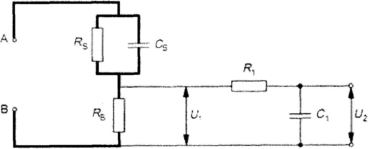
[0048] Capacitors are used to isolate the leakage current I earth =I e1 +I e2, in I e1 and I e2 In the loop, as long as Cs1 and Cs2 are small enough, I can also be suppressed earth TC0 In this way, the isolation of the primary side and the secondary side is realized. Use measurement network Z for actual testing TC E.g image 3 , where Rs=1.5kΩ, R B = 500Ω, R 1 = 10kΩ, C 1 =22nF, C S =220nF). When V TC =U 2 TC0 (For example, for audio and video products applicable to IEC60950, and V TC When the frequency is between DC~100kHz, V TC0 =0.35Vpk), it is safe. Therefore if Z TC replace Figure 5 The human body in the detected image 3 Middle V TC TC0 , then the present invention can suppress the leakage current and realize the isolation of the primary side and the secondary side. ...


PUM


Abstract

The invention discloses an electric energy isolation transmission method and an isolation transmission device, which belong to the fields of electric energy isolation transmission and methods. The method is as follows: an isolation transmission circuit comprising a capacitor realizes the electric isolation between original auxiliary sides, suppresses leakage current between the original auxiliarysides and transmits power. The device comprises the isolation transmission circuit, wherein the isolation transmission circuit is mainly realized by the capacitor. The invention is applied to a powersupply, an adapter and a relevant product which have alternating-current or direct-current output and require lightness, thinness and high efficiency. The invention has small volume and is light, thin and practical; and meanwhile, the invention has high power transmission efficiency.

Description

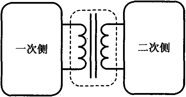
technical field [0001] The invention relates to an electric energy isolation transmission method and an isolation transmission device thereof, belonging to the field of electric energy isolation transmission methods. Background technique [0002] Such as figure 1 As shown, the common method of primary and secondary side isolation in the traditional power system is to use an isolation transformer. Such as figure 2 Shown is a schematic diagram of the leakage current (touch current / Touch current) circuit in the system using transformer isolation. It can be seen from the figure that the driving source of the leakage current loop is the grid voltage of 50 / 60Hz, but in practical applications, there is still a stray capacitance C between the primary and secondary sides of the isolation transformer. k , which leads to the fact that the primary and secondary sides cannot fully realize the ideal electrical isolation, only because C k Very small, so the leakage current between the...

Claims


Application Information

Patent Timeline
Patent Type & Authority Applications(China)
IPC IPC(8): H02M3/24H02M3/335
CPCH02M5/08H02M5/00
Inventor 孙巨禄朱经鹏徐明
Owner FSP POWERLAND TECH
Learn More