
Device and method for improved collection of dust in treatment of floor surfaces

A floor and dust technology, applied in a field, can solve problems such as bulky volume

Inactive Publication Date: 2010-07-14
HTC SWEDEN AB
View PDF4 Cites 2 Cited by
  • Summary
  • Abstract
  • Description
  • Claims
  • Application Information

AI Technical Summary

Problems solved by technology

[0005] The inconvenience in collecting sanding or polishing dust is that a vacuum cleaner of relatively high suction power is required to collect all sanding or polishing dust
In order to generate sufficient suction power, a large vacuum cleaner is required, which is thus heavy and bulky

Method used


Image

  • Device and method for improved collection of dust in treatment of floor surfaces
  • Device and method for improved collection of dust in treatment of floor surfaces
  • Device and method for improved collection of dust in treatment of floor surfaces

Examples


Embodiment Construction

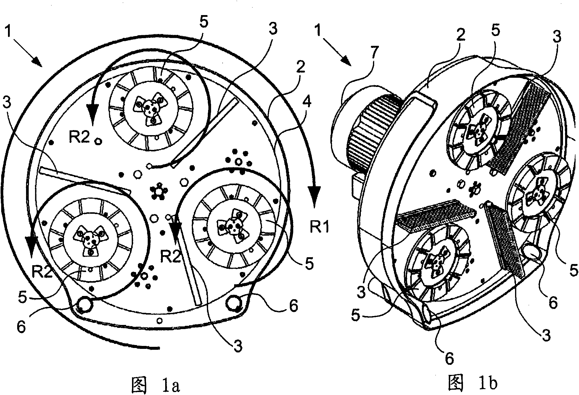
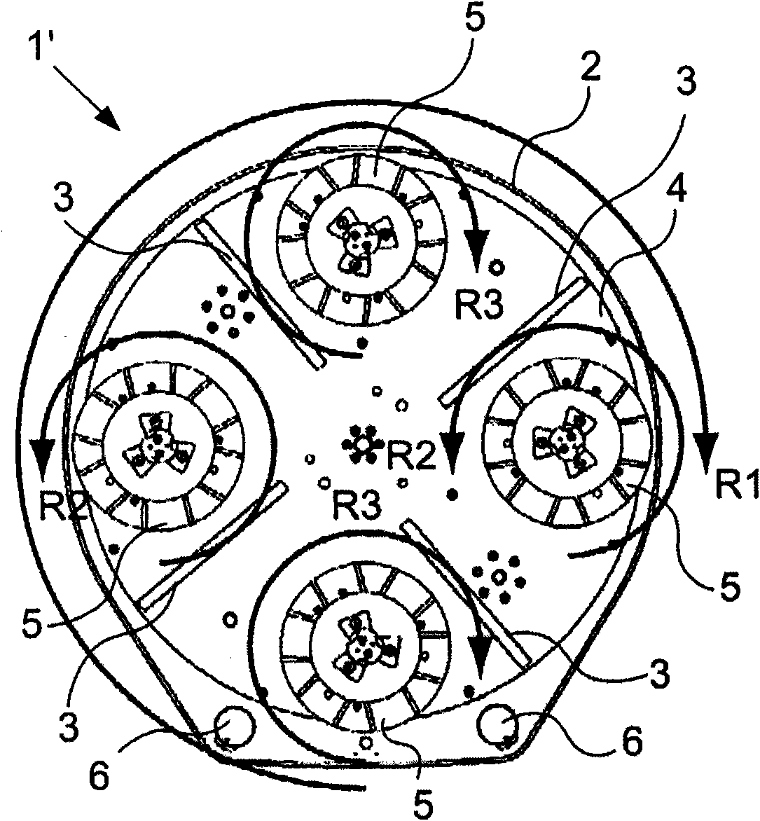
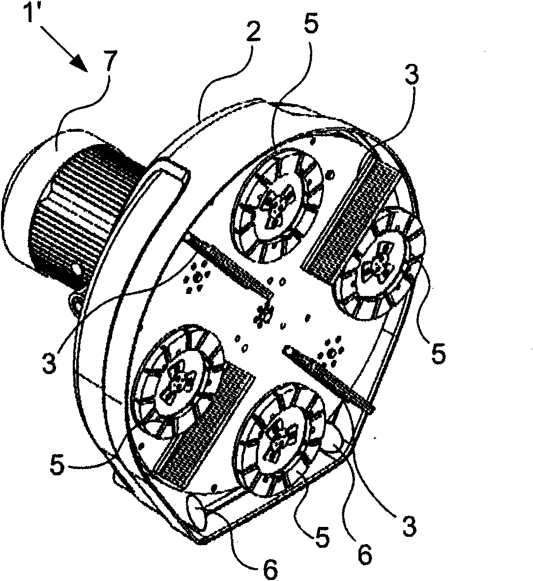
[0041] Figure 1a and 1b A first embodiment of a floor treatment device 1 is shown having a housing 2 delimiting a treatment space. In the processing space is accommodated a planetary disc 4 which is arranged to rotate in a first direction R1 relative to the frame of the machine (not shown). The planetary disc supports a plurality of process discs 5, each of which is rotatable in a second direction R2 relative to the planetary disc. Each processing disc 5 is arranged to support one or more grinding, polishing and / or cutting tools (not shown), typically 2-4. As a non-limiting example, the planetary disc 4 and the processing disc 5 may be configured to be driven by the drive motor 7 via a drive assembly such as that disclosed in WO9408752A1 or by an alternative drive assembly.

[0042] The processing space may have one or more suction inlets 6 to which one or more vacuum cleaners (not shown) may be connected to suck in particles (eg dust) generated during processing.

[0043]...


PUM


Abstract

A device for treating a floor surface comprises a casing which defines a treatment space. A stirrer, which is movably arranged in the treatment space, is designed and dimensioned to stir to up particles located on the floor surface.

Description

technical field [0001] The present invention relates to a device and a method for improving the collection of dust when treating eg floor surfaces. [0002] More particularly, the present invention relates to a method and apparatus that increases the efficiency of existing dust collection devices or reduces the power requirements of such dust collection devices. Background technique [0003] The present invention relates to machines for cutting, sanding and / or polishing surfaces, such as hard surfaces, which may comprise stone or stone-like materials, such as concrete, terrazzo, etc. This type of machine can also be used to treat other surfaces such as wood, linoleum, etc. [0004] When cutting, grinding and / or polishing a surface, particles of various sizes are generated which are usually collected. This collection can take place directly at the time of processing, usually with the aid of a dry vacuum cleaner, or with the aid of a wet vacuum cleaner when the process takes...

Claims


Application Information

Patent Timeline
IPC IPC(8): B24B55/10
CPCB24B55/10B24B7/186
Inventor 哈坎·锡塞尔
Owner HTC SWEDEN AB
Learn More