Pumping system

A pumping system and pumping technology, applied to pumps, pressure pumps, pump devices, etc., can solve problems such as narrow flow ranges

Active Publication Date: 2021-02-26
WEIR MINERALS NETHERLANDS BV
View PDF9 Cites 0 Cited by
  • Summary
  • Abstract
  • Description
  • Claims
  • Application Information

AI Technical Summary

Problems solved by technology

Some control over flow rate is possible through speed control of centrifugally driven fluid pumps, but this is limited because centrifugal pumps have a relatively narrow flow range over which they can operate efficiently and reliably

Method used


Image

  • Pumping system
  • Pumping system
  • Pumping system

Examples


Embodiment Construction

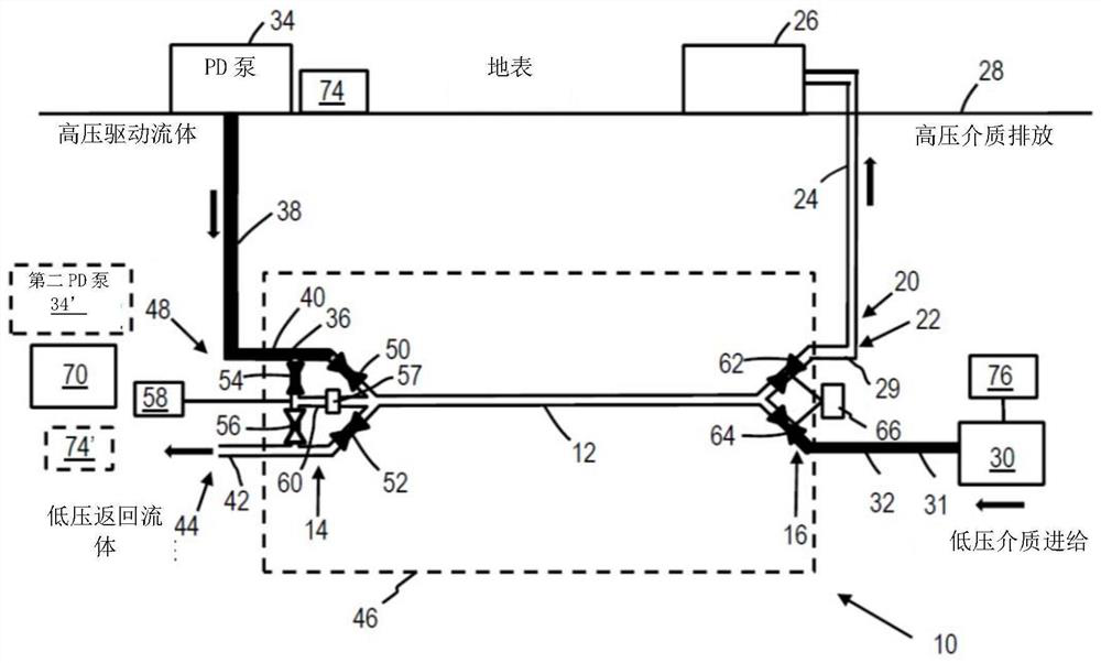
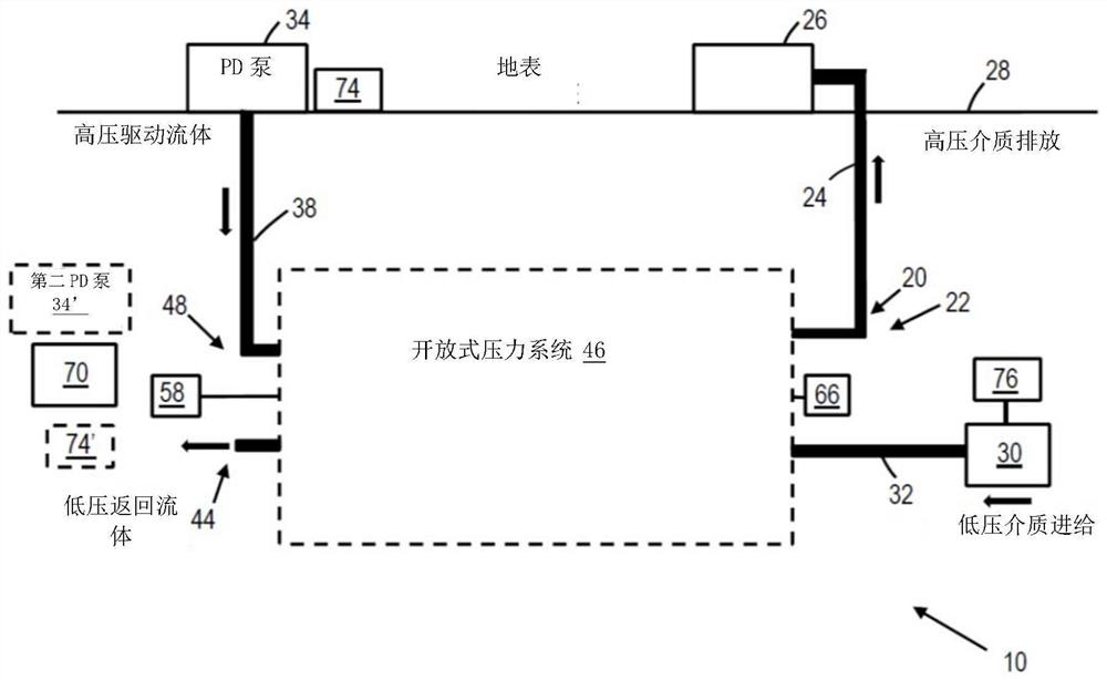
[0115] first reference figure 1 , which is a simplified schematic diagram of a pumping system 10 according to a first embodiment of the present invention. In a typical embodiment, most or all of the pumping system 10 is located at an altitude lower than the final delivery point where the pumping system 10 will deliver the medium. In this embodiment, the medium comprises ore particles in the size range of 1 to 100 mm in a liquid carrier to produce a slurry which entrains and suspends the ore particles.

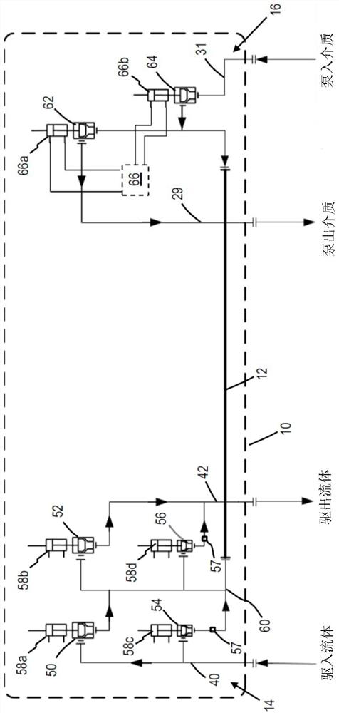
[0116] The pumping system 10 comprises a single pressure exchange chamber 12 having valve means 14 , 16 at each end thereof, ie a drive fluid valve means 14 and a pumped medium valve means 16 .

[0117] also refer to Figure 1A , which is a simplified schematic diagram of the pressure exchange chamber 12 showing the valve means 14, 16 in more detail.

[0118] A pressurized discharge 20 is provided at a delivery end 22 of the system 10 . In this embodiment, the pressurized d...


PUM


Abstract

A pumping system for pumping a medium is described. The system comprises: at least one transverse pressure exchange chamber, but preferably multiple pressure exchange chambers. Each pressure exchangechamber has a valve arrangement at each end. The system also includes a pressurised discharge at a delivery end of the system and a filling mechanism operable to fill the pressure exchange chamber with the medium. A positive displacement pump is operable to pump a driving fluid in direct contact with the medium so that the medium is pumped from the pressure exchange chamber to the pressurised discharge. A method of pumping a medium is also described.

Description

technical field [0001] The invention relates to a pumping system. In particular, although not exclusively, the present invention relates to a pumping system for use in the mineral processing industry. Background technique [0002] In the mineral processing industry, one problem involves transporting ore from an underground or subsea location to surface level. In most such applications, the transport involves raising the ore vertically and transporting the ore horizontally. [0003] For relatively small vertical distances, belt or truck transport arrangements are the primary transport methods. For underground mines, the primary method of transport is skip hoisting, where the skip is lifted to the surface after being loaded with ore underground. In seabed mining, which is a relatively new application, various methods are being considered, such as skip lift, air lift or hydraulic lift. In hydraulic lift, ore is mixed with a carrier fluid, such as water, to form a suspension...

Claims


Application Information

Patent Timeline
Patent Type & Authority Applications(China)
IPC IPC(8): E21C50/00E21F13/04F04B23/04F04F1/08F04F1/14
CPCF04F1/08E21C50/00E21F13/042F04F13/00F04B47/04E21B43/129F04F1/06E21B17/01E21B43/29
Inventor 鲁多法·凡瑞思维克
Owner WEIR MINERALS NETHERLANDS BV
Why Eureka
Try Eureka