Drying tower with positive-negative shunt structures and drying method thereof

A drying tower, tower-type drying technology, applied in the fields of application, food preparation, food science, etc., to achieve the effect of avoiding particle adhesion and avoiding uneven drying

Inactive Publication Date: 2010-07-21
SHANGHAI YI CHEN INFORMATION TECH DEV
View PDF8 Cites 2 Cited by
  • Summary
  • Abstract
  • Description
  • Claims
  • Application Information

AI Technical Summary

Problems solved by technology

Although the powder and granular materials are divided into several groups, which can promote the uniform drying of the materials,

Method used


Image

  • Drying tower with positive-negative shunt structures and drying method thereof
  • Drying tower with positive-negative shunt structures and drying method thereof
  • Drying tower with positive-negative shunt structures and drying method thereof

Examples


Example Embodiment

[0078] Example 1:

[0079] A drying tower comprising the following parts:

[0080] according to figure 1 :

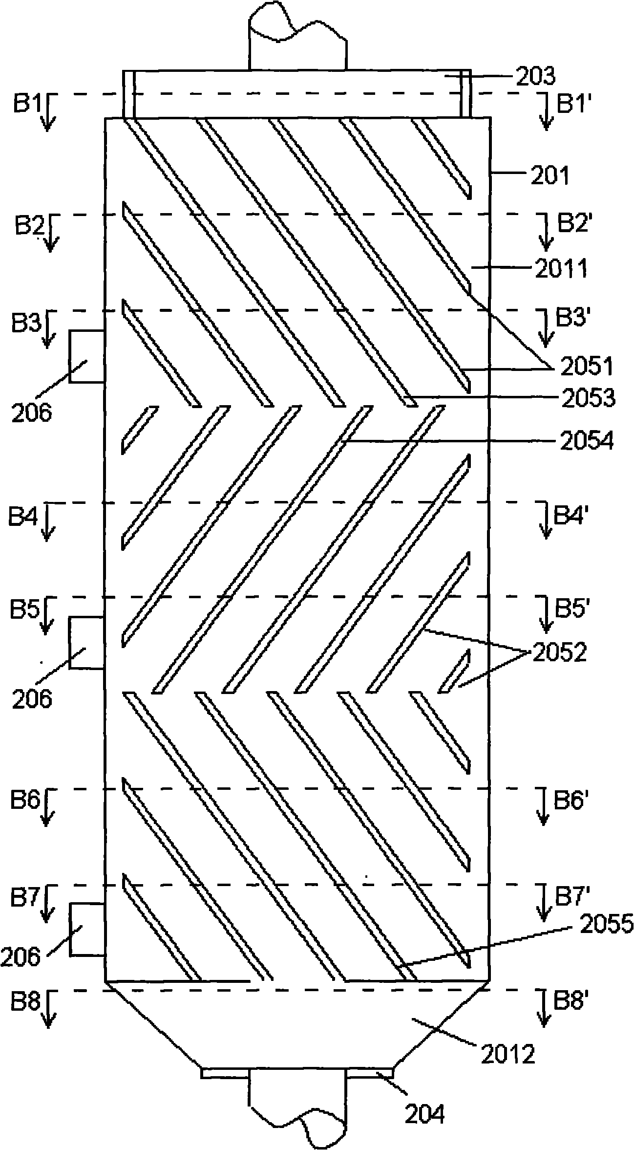
[0081] A drying tower, comprising a shell 201 , a rotating shaft 202 , a material inlet 203 , a material outlet 204 , and a flow distribution channel 205 .

[0082] The casing 201 includes a cylindrical tower drying chamber 2011 at the upper part and a conical storage chamber 2012 at the lower part.

[0083] according to figure 1 :

[0084] The distribution material channel 205 includes a group of distribution structures 2050 rotating around the rotating shaft 202 .

[0085] The distribution material channel 205 includes 2 to 6 distribution structures 2050 , and the distribution structures 2050 are divided into a forward distribution structure 2051 and a reverse distribution structure 2052 . The forward flow distribution structures 2051 and the reverse flow distribution structures 2052 are arranged alternately.

[0086] according to Figure 4a , 4b , 4c, 4d, 4e...

Example Embodiment

[0129] Embodiment two:

[0130] Adopt the following technical parameters to improve embodiment one:

[0131] The distribution material channel 205 includes two distribution structures 2050

[0132] Each shunt structure 2050 includes 4 shunt gates.

[0133] The inclination angle b2 between the forward shunt gate of the forward shunt structure 2051 and the horizontal plane is 135°.

[0134] The inclination angle b3 between the reverse shunt gate of the reverse shunt structure 2052 and the horizontal plane is 45°.

[0135] Wherein the ratio of the distance L1 to L2 between the reverse shunt grid and two adjacent forward shunt grids is 1:1. The ratio of the vertical length of the interlaced area between the reverse shunt grid and the adjacent forward shunt grid to the distance L3 between two adjacent forward shunt grids and L1+L2 is 1:6.

[0136] The angle formed between the air outlet 2063 and the horizontal plane is 42°.

Example Embodiment

[0137] Embodiment four:

[0138] Adopt the following technical parameters to improve embodiment one:

[0139] The distribution material channel 205 includes three distribution structures 2050

[0140] Each shunt structure 2050 includes 8 shunt gates.

[0141] The inclination angle b2 between the forward shunt gate of the forward shunt structure 2051 and the horizontal plane is 129°.

[0142] The inclination angle b3 between the reverse shunt gate of the reverse shunt structure 2052 and the horizontal plane is 51°.

[0143] Wherein the ratio of the distance L1 to L2 between the reverse shunt grid and two adjacent forward shunt grids is 1:1. The ratio of the vertical length of the interlaced area between the reverse shunt grid and the adjacent forward shunt grid to the distance L3 between two adjacent forward shunt grids and L1+L2 is 1:4.

[0144] The angle formed between the air outlet 2063 and the horizontal plane is 48°.


PUM

PropertyMeasurementUnit
Central angleaaaaaaaaaa

Abstract

The invention discloses a drying tower with positive-negative shunt structures and a drying method thereof. The drying tower comprises a shell, a rotary shaft, a feed port, a discharge port, a shunt material channel and a rotational wind generation device, wherein the rotary shaft is arranged in the center of the shell and is provided with a shaft shell, a shaft cavity encircled by the shaft shell and a group of one-way holes arranged on the shaft shell; the shunt material channel is formed by a group of shunt structures which rotate around the rotary shaft serving as the shaft center, and the shunt structures are divided into the positive shunt structures and the negative shunt structures, which are alternately arranged; and the shunt structures are formed by a group of shunt gates comprising 4 to 32 shunt gates, and each shunt gate is an axon structure taking the rotary shaft as the shaft center and extending outward along the radial direction of the axon structure.

Description

technical field [0001] The invention relates to a drying tower, in particular to a drying tower with a forward and reverse split flow structure. [0002] The invention also relates to a drying method using a drying tower with a forward-backward split structure for drying. Background technique [0003] During the processing of reconstituted rice, it is necessary to dry and cool the reconstituted rice particles after extrusion and cutting. However, the reconstituted rice granules after extrusion and cutting have higher water content and higher temperature, and the starch component therein will undergo gelatinization under the conditions of high temperature and high humidity, so that the outer surface of the reconstituted rice granules has a higher viscosity. This also resulted in a greater degree of sticking between the reconstituted rice grains. [0004] For the drying of solid granular materials, tower dryers, drum dryers, etc. are often used to take away the moisture of s...

Claims


Application Information

Patent Timeline
IPC IPC(8): A23L1/182A23L7/196
Inventor 刘英
Owner SHANGHAI YI CHEN INFORMATION TECH DEV
Why Eureka
Try Eureka