
Fly ash dryer

A dryer and fly ash technology, applied in the direction of dryers, drying, non-progressive dryers, etc., can solve the problems of affecting later use and uneven drying, so as to improve uniformity and avoid affecting use , to avoid uneven drying effect

Pending Publication Date: 2020-07-28
盐城市双泰热能设备科技有限公司
View PDF2 Cites 2 Cited by
  • Summary
  • Abstract
  • Description
  • Claims
  • Application Information

AI Technical Summary

Problems solved by technology

[0004] The purpose of the present invention is to solve the problem that the existing dryer does not grind the coal ash, which causes some larger particles of coal ash to be mixed with smaller particles of coal ash, which easily causes uneven drying and affects the later stage. Disadvantages of Using a Raised Fly Ash Dryer

Method used


Image

  • Fly ash dryer
  • Fly ash dryer
  • Fly ash dryer

Examples


Embodiment 1

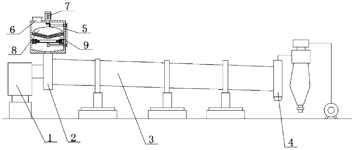
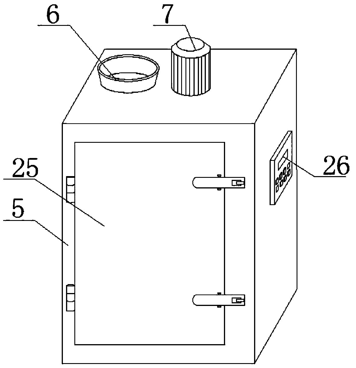
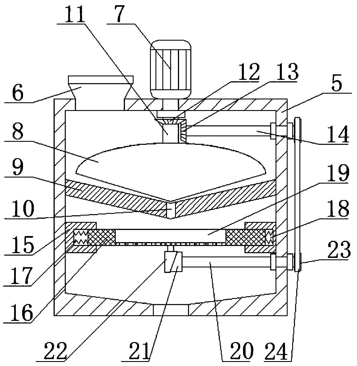
[0023] refer to Figure 1-4 , Fly ash dryer, including heating equipment 1, feeding equipment 2, supporting roller equipment, drying kiln body 3, transmission equipment, gear supporting roller equipment, discharging equipment 4, cyclone separation equipment and induced draft fan, feeding equipment 2 A charging box 5 is connected to it, and a fixed rolling disc 9 is fixedly installed in the charging box 5. The top of the feeding box 5 is fixedly connected with a servo motor 7, and the output shaft of the servo motor 7 is fixedly installed with a rolling shaft 11, and the rolling shaft 11 is connected with the feeding box. 5 Rotational connection, the bottom of the rolling shaft 11 is fixedly equipped with a conical milling disc 8, the conical milling disc 8 is compatible with the fixed milling disc 9, the conical structure of the fixed milling disc 9, the inclination angle of the conical milling disc 8 is greater than that of the fixed milling disc 9 Angle, the particles can be...

Embodiment 2

[0030] refer to Figure 1-4 , Fly ash dryer, including heating equipment 1, feeding equipment 2, supporting roller equipment, drying kiln body 3, transmission equipment, gear supporting roller equipment, discharging equipment 4, cyclone separation equipment and induced draft fan, feeding equipment 2 A charging box 5 is connected to it, and a fixed rolling disc 9 is fixedly installed in the charging box 5 by welding. The top of the charging box 5 is fixedly connected with a servo motor 7 by screws, and the output shaft of the servo motor 7 is fixedly installed with a rolling shaft 11 by welding. The finale shaft 11 is rotatably connected with the charging box 5, and the bottom of the rolling shaft 11 is fixedly installed with a conical milling disc 8 by welding. The conical milling disc 8 is compatible with the fixed milling disc 9. The angle of inclination is greater than the angle of inclination of the fixed mill pan 9, and the particles can be crushed. The central position o...


PUM


Abstract

The invention belongs to the technical field of coal ash grinding and filtering and particularly discloses a fly ash dryer. The following scheme is proposed against the problems that an existing dryeris unavailable to grind coal ash, consequently some coal ash with large particles and coal ash with small particles are mixed together, drying is prone to being non-uniform, and subsequent use is affected. According to the scheme, the fly ash dryer comprises heating equipment, charging equipment, riding wheel equipment, a drying kiln, transmission equipment, geared riding wheel equipment, discharging equipment, cyclone separation equipment and an induced draft fan, wherein a charging box is arranged on the charging equipment in a communicating mode, a fixed grinding disk is fixedly mounted inthe charging box, a servo motor is fixedly connected to the top of the charging box, a grinding shaft is fixedly mounted on an output shaft of the servo motor, the grinding shaft is rotationally connected with the charging box, a conical grinding disk is fixedly mounted at the bottom of the grinding shaft, and the conical grinding disk is matched with the fixed grinding disk. Through the fly ashdryer, the coal ash can be ground and screened, the uniformity of the coal ash can be improved, and drying non-uniformity in a later period is avoided.

Description

technical field [0001] The invention relates to the technical field of coal ash grinding and filtration, in particular to a fly ash dryer. Background technique [0002] Fly ash can be used as an admixture for cement, mortar, and concrete, and becomes a component of cement and concrete. Fly ash can be used as a raw material to replace clay to produce cement clinker, and to manufacture sintered bricks, autoclaved aerated concrete, and foam. Concrete, hollow bricks, sintered or non-sintered ceramsite, paving roads; at present, in areas where the cement industry is developed, such as Jiangsu, Shandong, Zhejiang, Hebei and other places, dry fly ash is used as a mixture of cement production, and the market is good. The physical and chemical properties of wet fly ash are basically the same as those of dry fly ash, but due to the large water content (up to 45%), it cannot meet the requirements of cement production and is not affected by the market. Favored, can only be piled up in ...

Claims


Application Information

Patent Timeline
Patent Type & Authority Applications(China)
IPC IPC(8): F26B1/00F26B11/04F26B23/00F26B25/00B02C2/10B02C21/00B02C23/16
CPCF26B1/00F26B11/04F26B23/00F26B25/002B02C2/10B02C23/16B02C21/00B02C2023/165
Inventor 严书刚
Owner 盐城市双泰热能设备科技有限公司
Learn More