

Flag hoisting and lowering mechanism of flag pole
A flagpole and drive mechanism technology, applied in the field of flagpoles, can solve problems affecting the effect of flag flying, twisted or entangled coils, delays in the flag-raising process, etc., to achieve the effects of increased decoration, stable and reliable operation, and a high degree of automation
- Summary
- Abstract
- Description
- Claims
- Application Information
AI Technical Summary
Problems solved by technology
Method used
Image

Examples
Embodiment Construction
[0025] The following examples are further supplements and illustrations of the present invention, and do not constitute any limitation to the present invention.
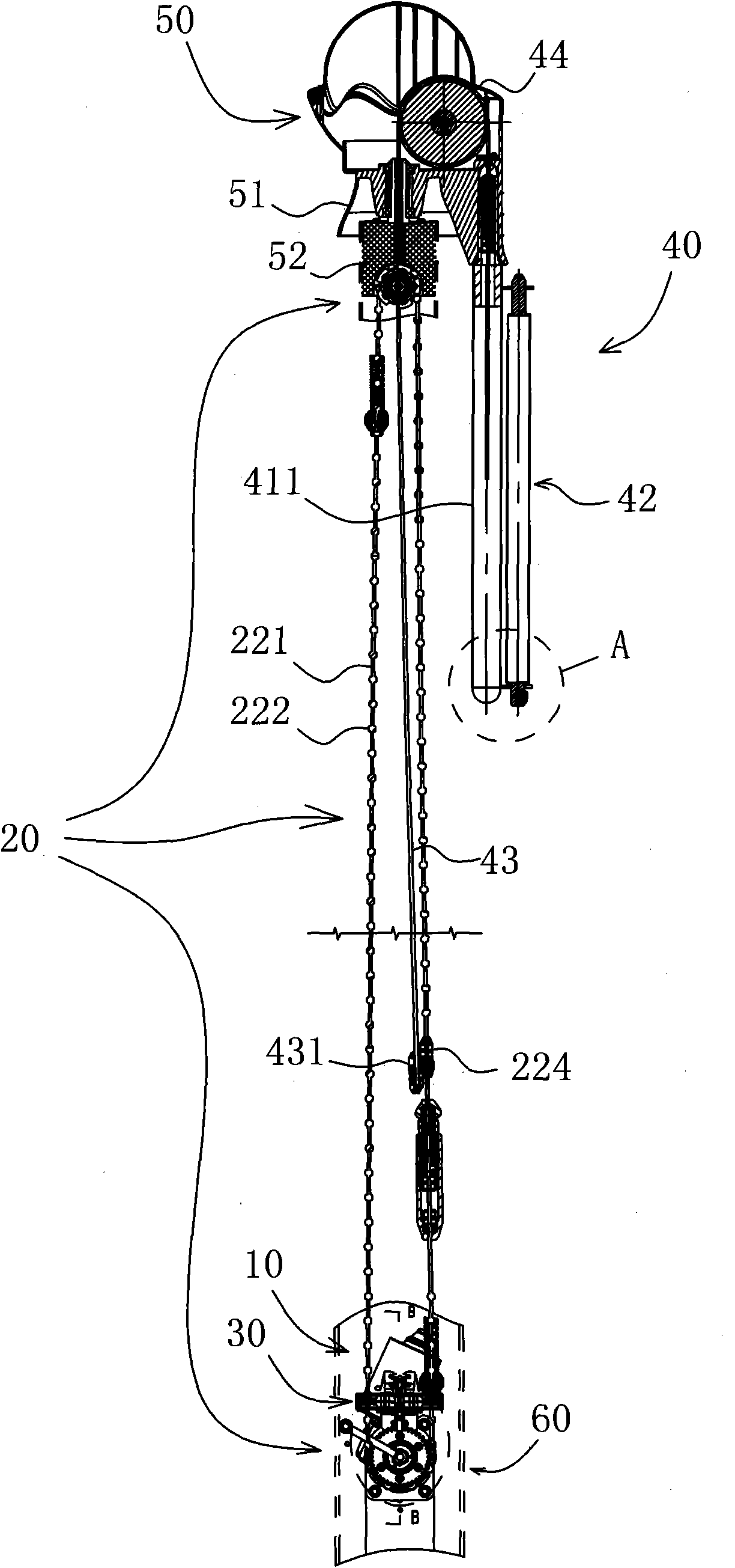
[0026] refer to figure 1 , The lifting flag mechanism of the flagpole of the present invention includes a driving mechanism 10 , a transmission mechanism 20 , a lifting flag positioning mechanism 30 , a flag hanging assembly 40 , a spherical crown assembly 50 and a flagpole 60 .
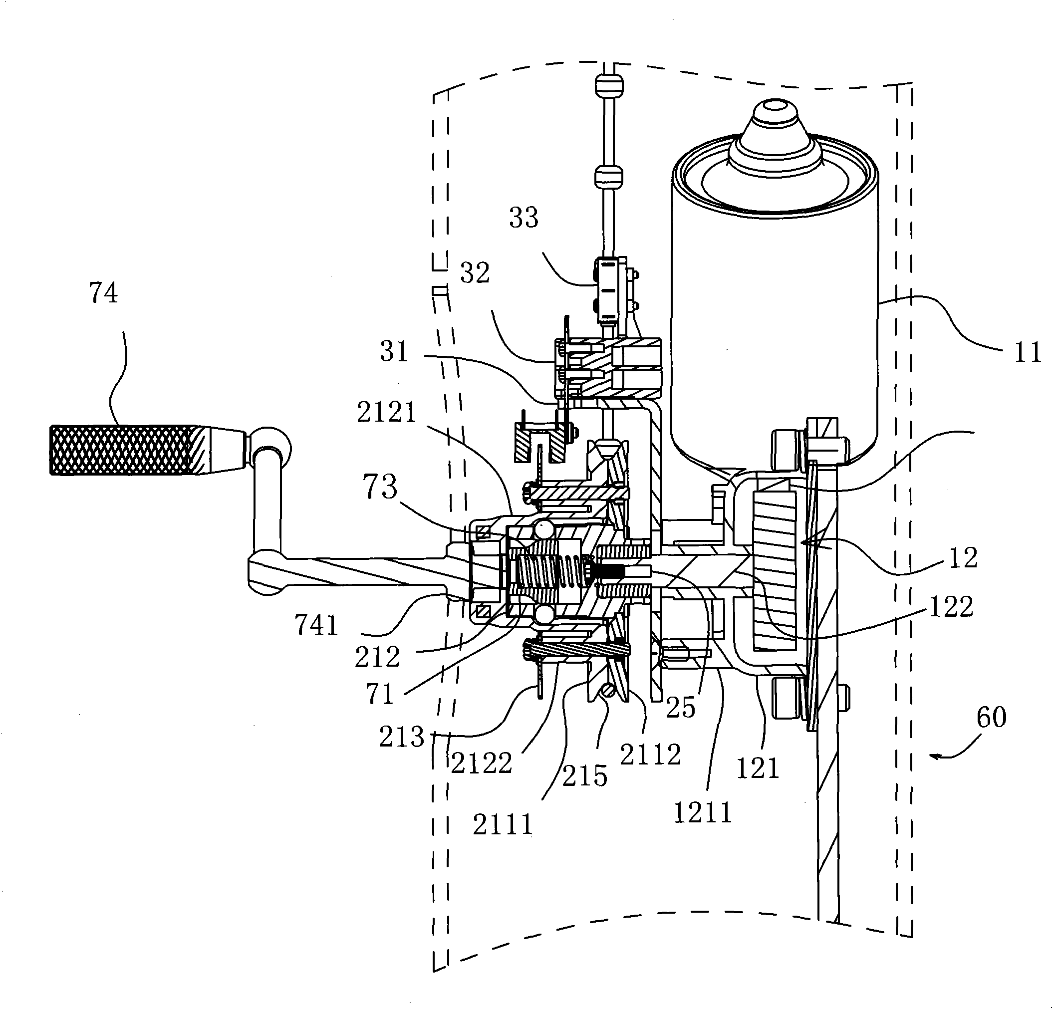
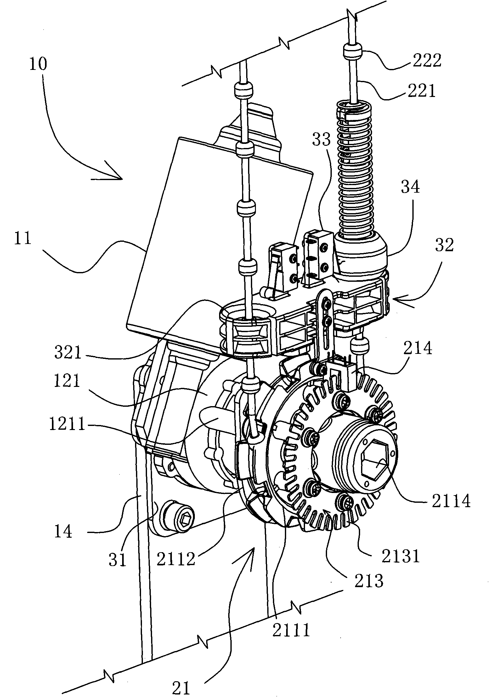
[0027] Described drive mechanism 10 structures such as Figure 2A ~ Figure 2C As shown, the driving mechanism 10 is mounted on the inner bottom of the flagpole 60 , which includes a motor 11 , a worm gear 12 and a worm 13 , wherein the motor 11 is a columnar reversible motor, which is arranged along the axial direction of the flagpole 60 . The worm 13 is integrated with the motor shaft and meshes with the worm gear 12. The motor 11, the worm gear 12 and the worm 13 are selected from a commercially available integrated worm gear reduction m...
PUM
 Abstract
Description
Claims
Application Information