

Laser pollution sensor
A technology of sensors and lasers, applied in the direction of instruments, scientific instruments, optical testing defects/defects, etc., can solve inaccurate problems and achieve the effect of solving inaccuracies
- Summary
- Abstract
- Description
- Claims
- Application Information
AI Technical Summary
Problems solved by technology
Method used
Image

Examples
Embodiment Construction
[0025] The present invention is described in detail below in conjunction with accompanying drawing:
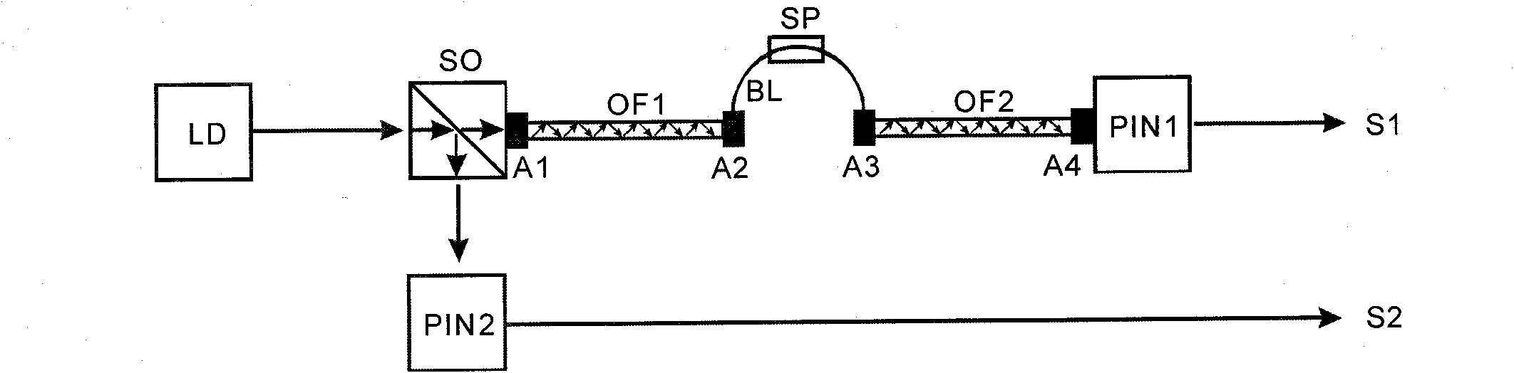
[0026] like image 3 As shown, the present invention includes laser LD, optical splitter SO, two optical fiber bundles (OF1, OF2), optical fiber, quartz rod BL, equivalent regulator SP, two photoelectric converters (PIN1, PIN2), four optical connections (A1, A2, A3, A4), the two ends of each optical fiber bundle are fixedly connected to an optical connector, the laser light generated by the laser LD enters the optical splitter SO, and the split end of the optical splitter SO is connected to the quartz rod BL through an optical fiber bundle OF1 , the quartz rod BL is connected to the photoelectric converter PIN1 through another optical fiber bundle OF2, the other end of the beam splitter SO is connected to another photoelectric converter PIN2 through an optical fiber, and the equivalent adjuster SP is installed on the quartz rod BL. The optical splitter SO is made of quartz cr...
PUM
| Property | Measurement | Unit |
|---|---|---|
| Diameter | aaaaa | aaaaa |
| Length | aaaaa | aaaaa |
| Arc diameter | aaaaa | aaaaa |
Abstract
Description
Claims
Application Information