Grinding center and method for the simultaneous grinding of multiple crankshaft bearings

A crankshaft and main bearing technology, which is applied to the parts of grinding machine tools, machine tools designed for grinding the rotating surface of workpieces, grinding machines, etc., can solve the problem of large space control device consumption and other problems, and achieve the effect of reducing space occupation

Active Publication Date: 2010-07-21
ERWIN JUNKER MASCHNINENFAB
View PDF4 Cites 10 Cited by
  • Summary
  • Abstract
  • Description
  • Claims
  • Application Information

AI Technical Summary

Problems solved by technology

The design of a grinding center with two separate cross slides requires a great deal of space as well as an enormous outlay on components and associated controls, even for the machining of only two bearings.

Method used


Image

  • Grinding center and method for the simultaneous grinding of multiple crankshaft bearings
  • Grinding center and method for the simultaneous grinding of multiple crankshaft bearings
  • Grinding center and method for the simultaneous grinding of multiple crankshaft bearings

Examples


Embodiment Construction

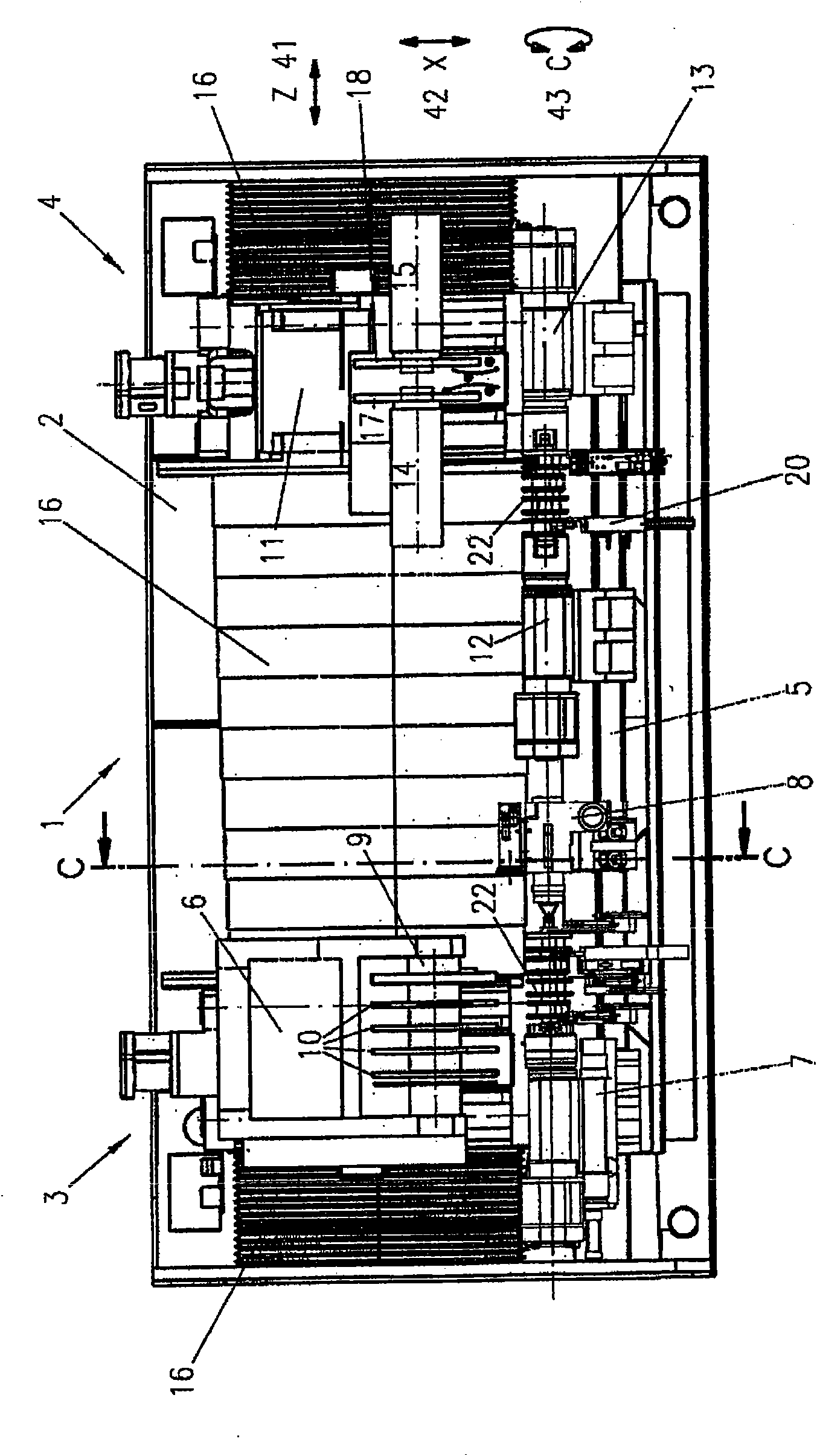
[0032] exist figure 1 A plan view of a grinding center designed as a grinding unit 1 is shown in . The grinding unit has a common machine tool 2 on which two stations 3 , 4 are arranged for machining the crankshaft 22 by grinding. The stations 3 , 4 have a common grinding table 5 on which a holding device and a drive device for the crankshaft 22 are located. The grinding unit usually also has a hood and a loading and unloading device for feeding in and removing the crankshaft 22 and transporting it from the first station 3 to the second station 4 . However, the loading and unloading device is figure 1Not shown, nor are the CNC control with input keys and the hydraulic and / or pneumatic supply.

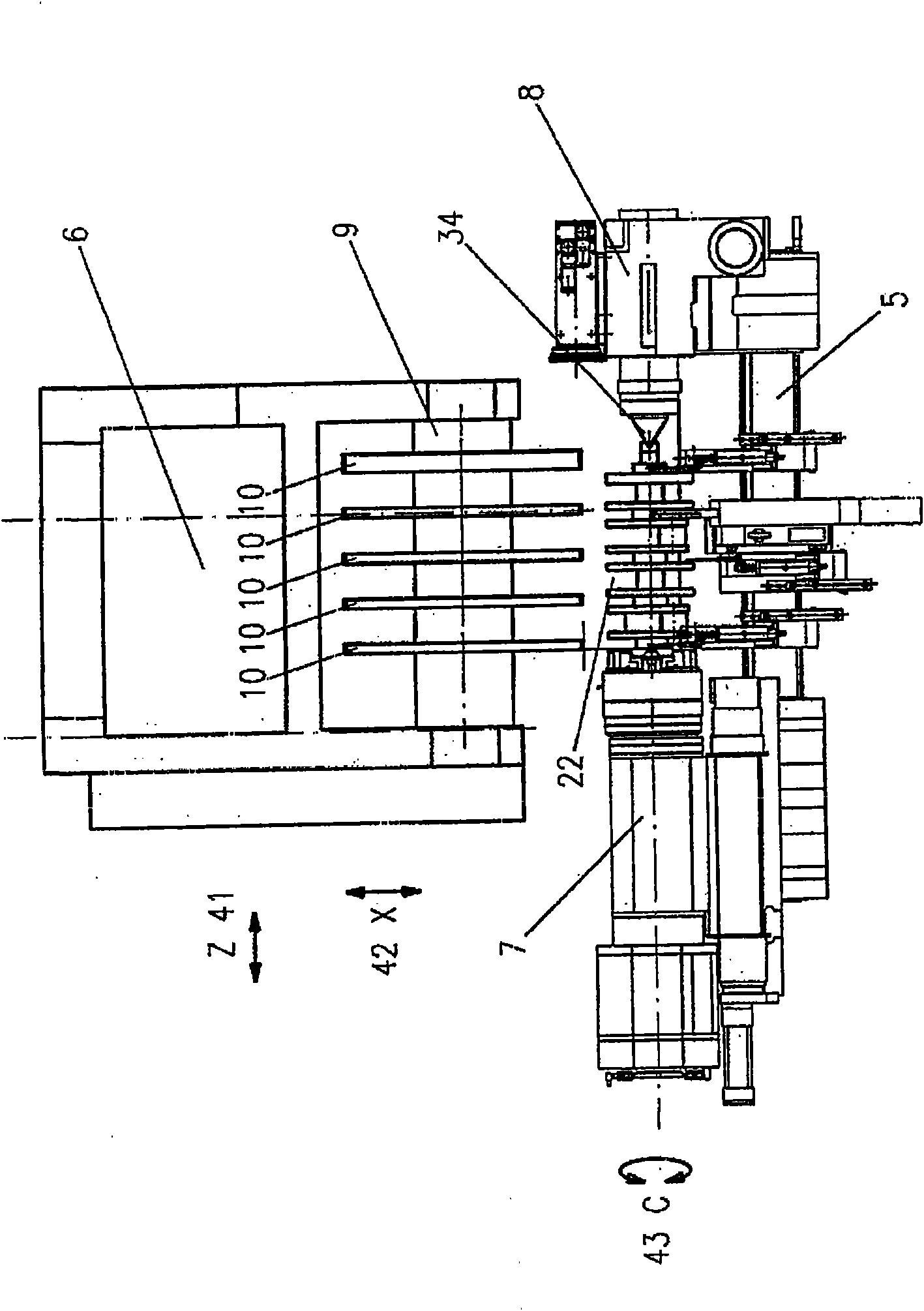
[0033] exist figure 2 The first station 3 of the grinding unit 1 shown separately in FIG. 2 is used for grinding the main bearing 23 of the crankshaft 22 . For the sake of illustration, the most important functional parts of the first station 3 are shown in the auxiliary figure "m...


PUM


Abstract

The invention relates to a grinding center for the simultaneous grinding of multiple main bearings and rod bearings and / or central sections of crankshafts (22). Two rod bearing grinding spindles (14, 15), wherein the first can be displaced only in the Z direction and the second can be minimally displaced only in the X direction, are mounted on a common rod bearing crossslide (11). In the final phase of the grinding, a correction of dimension deviation between the two machined rod bearings is carried out via a separate control of the second rod bearing grinding spindle (15), as a dimension or roundness correction. The deviations are detected by measuring devices.

Description

technical field [0001] The invention relates to a grinding center for grinding a crankshaft having main bearings and connecting rod bearings, wherein a plurality of main bearings and connecting rod bearings are ground simultaneously. Background technique [0002] These grinding centers are used for rough and / or finish grinding of crankshafts in high piece quantities. Here, crankshafts are usually used in four-cylinder single-row engines in the automotive industry, wherein every two connecting rod bearings are arranged at the same angular position with respect to the longitudinal axis of the crankshaft. In order to increase productivity, the two rod bearings are ground simultaneously (parallel in time). Such operating methods are described, for example, in EP1044764A2 and EP1088621B1. [0003] Simultaneous grinding of several bearings for the main bearing of a crankshaft is already known, for example, from US Pat. No. 3,487,588. The grinding spindle for the main bearing he...

Claims


Application Information

Patent Timeline
Patent Type & Authority Applications(China)
IPC IPC(8): B23Q15/16B23Q15/28B23Q17/22B24B5/42B24B19/12B24B49/03
CPCB24B49/03B24B19/125B24B5/42B23Q17/22
Inventor 埃尔温·容克尔
Owner ERWIN JUNKER MASCHNINENFAB
Why Eureka
Try Eureka