
Sound producing system

A technology of sound wave and electroacoustic converter, which is applied in the field of acoustics and can solve problems such as damage to electronic equipment

Inactive Publication Date: 2010-07-21
BOSE CORP
View PDF4 Cites 0 Cited by
  • Summary
  • Abstract
  • Description
  • Claims
  • Application Information

AI Technical Summary

Problems solved by technology

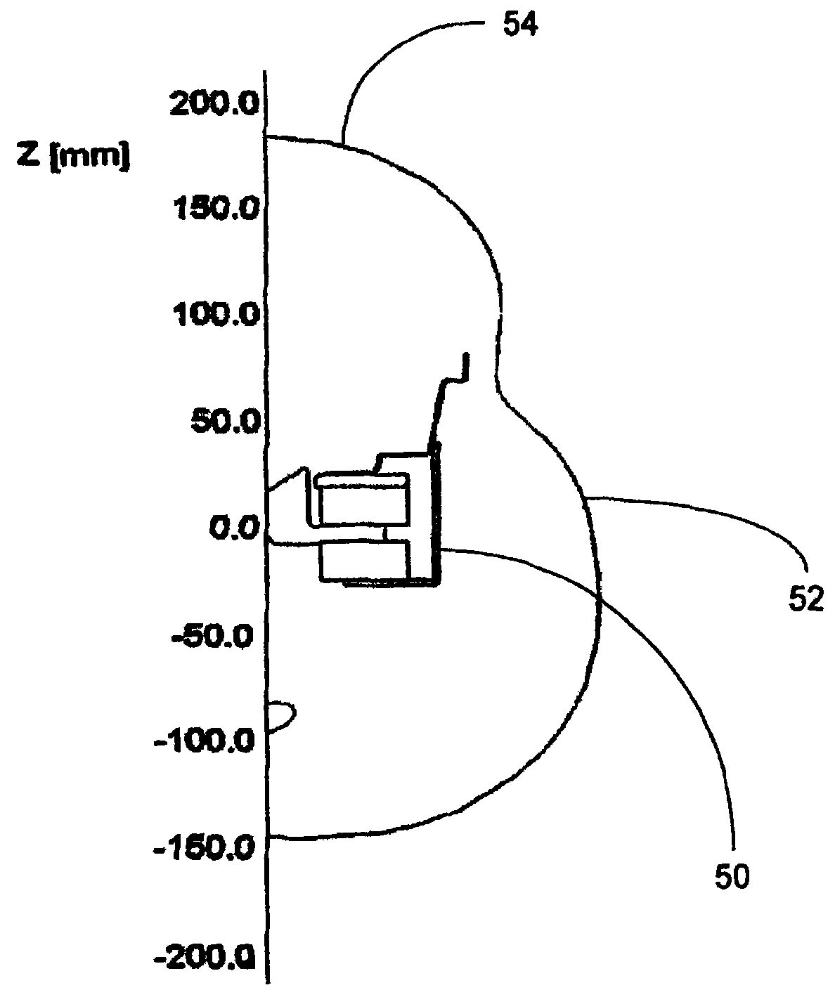
If the sound producing device is placed too close to another electronic device (for example, a video monitor), stray magnetic flux may damage that electronic device

Method used


Image

  • Sound producing system
  • Sound producing system
  • Sound producing system

Examples


Embodiment Construction

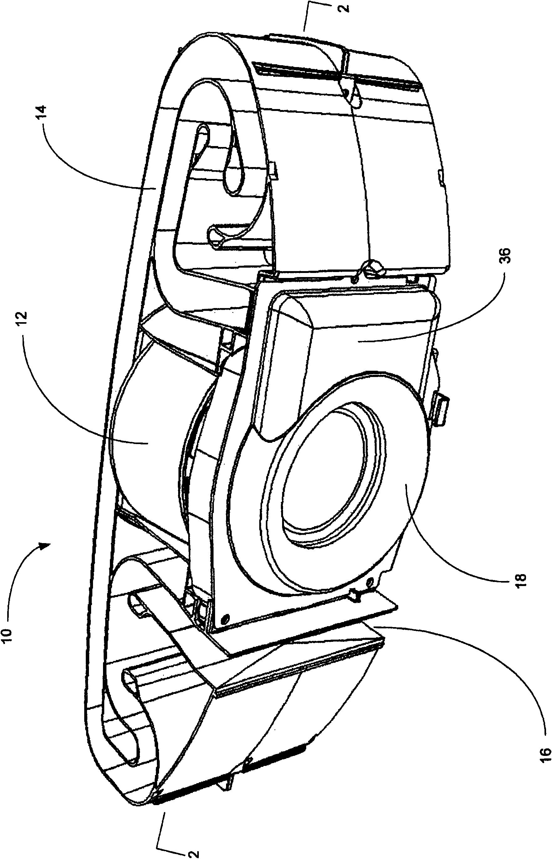
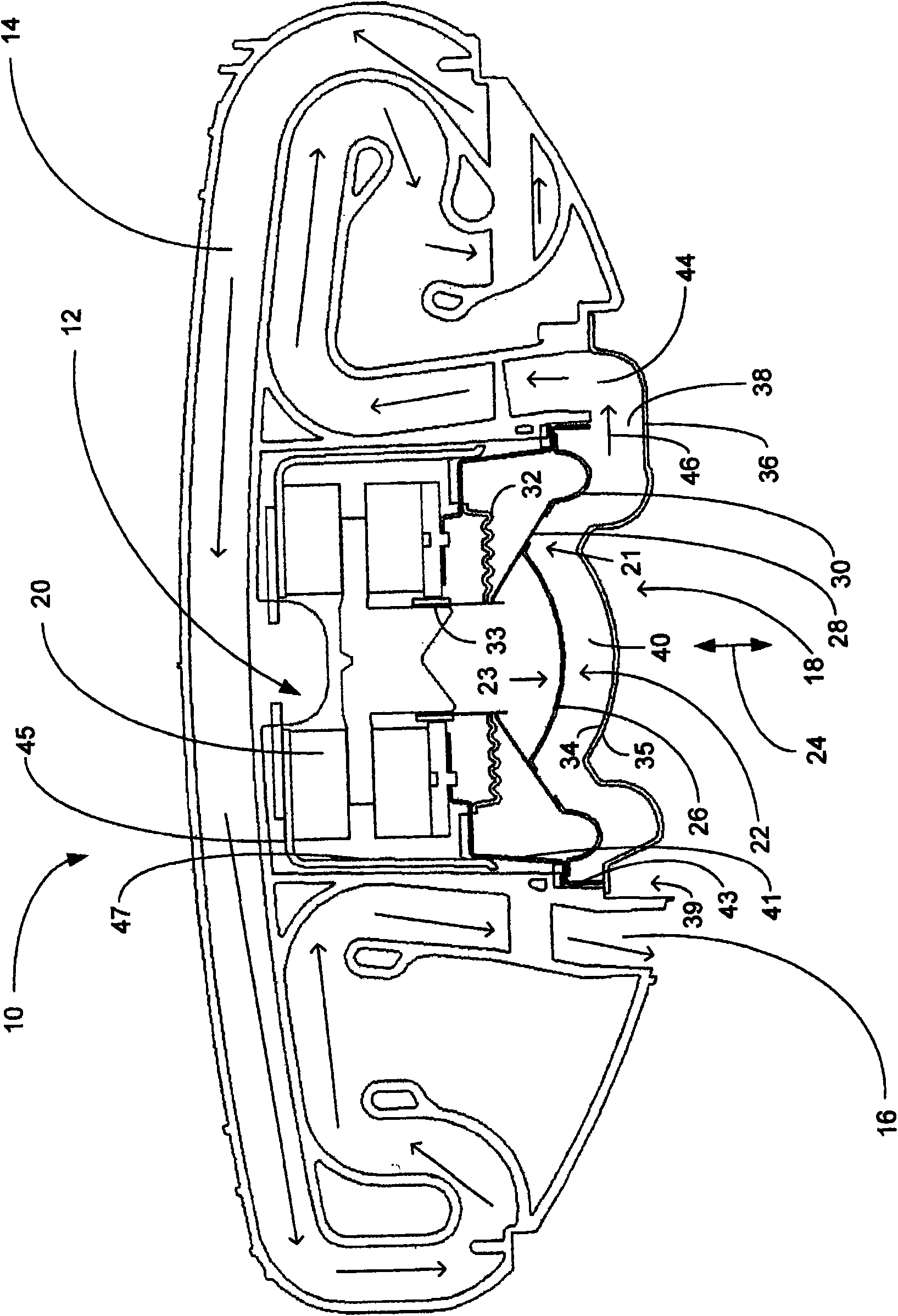
[0014] refer to figure 1 , shows a sound generation system 10 for playing audio out loud. The housing of system 10 has been removed for ease of viewing. System 10 includes an electro-acoustic transducer 12, in this example a woofer. The system has a waveguide 14 which includes a waveguide outlet 16 . The sound waves generated by the system are sent by the waveguide 14 and the waveguide outlet 16 to the listening environment outside the system. A converter housing 18 is positioned adjacent to the converter 12 and secured to the frame of the system 10 . The enclosure is a solid airtight structure, preferably made of a magnetically permeable material such as 1.5 mm thick cold rolled steel (CRS). An example of a CRS with a permeability of about 2.5k N / A 2 Grade 1010 (low carbon steel). Other materials from which the cover 16 can be made include 2 High magnetic permeability nickel-iron alloy with a magnetic permeability of about 5k N / A 2 Permalloy, with a magnetic permeabil...


PUM


Abstract

A sound producing system includes an electro-acoustic transducer having an electro-magnetic motor for moving a diaphragm of the transducer back and forth to create acoustic waves. The diaphragm has a surface that includes one or more of a surface of a dust cap of the diaphragm, a surface of a cone of the diaphragm, and a portion of a surface of a surround (30) of the diaphragm. A solid gas impermeable cover faces the diaphragm surface and has a surface which faces the diaphragm surface. At least a portion of the cover surface has a contour which is substantially the same as a contour of the diaphragm surface. The system includes an asymmetric exit for the acoustic waves to leave a volume defined between the diaphragm surface and the cover surface.

Description

technical field [0001] The present invention belongs to the field of acoustics, and more particularly relates to a sound generating device. Background technique [0002] The goal of some developers of sound generating devices is to provide more sound power in a smaller product package. Achieving a smaller product package can be challenging, especially if waveguides are used to increase the low frequency output of the device. Typically, electro-acoustic transducers launch sound waves into waveguides. The air volume located near the converter increases the size of the device. If the volume of air near the converter can be minimized, the size of the device can be reduced. [0003] Delivering more acoustic power in a smaller product package usually involves using more powerful electromagnetic motors in electroacoustic transducers. Using a more powerful motor increases the amount of stray flux generated by the motor extending beyond the product package. If the sound emitting...

Claims


Application Information

Patent Timeline
Patent Type & Authority Applications(China)
IPC IPC(8): H04R1/28H04R1/02
CPCH04R1/023H04R1/2857H04R2209/022
Inventor A·T·格拉夫R·P·帕克J·R·布拉斯
Owner BOSE CORP
Learn More