Drawbench

A wire-drawing machine and wire-drawing technology, applied in the field of wire-drawing machines, can solve the problems affecting the wire-drawing accuracy, the length of the remaining tail rod, and the uncontrollable air convection, etc., to achieve the effect of eliminating mechanical disturbance and improving the drawing accuracy

Inactive Publication Date: 2010-07-28
方强
View PDF5 Cites 5 Cited by
  • Summary
  • Abstract
  • Description
  • Claims
  • Application Information

AI Technical Summary

Problems solved by technology

[0003] At present, this kind of wire drawing equipment has the following problems: 1) because the preform rod is moving during the wire drawing process, there is always mechanical vibration, which affects the wire drawing accuracy; 2) when drawing a tubular preform rod, because the heating zone is in At the lower end of the tube, the air convection in the tube cannot be controlled, resulting in low wire drawing accuracy; 3) Due to the air convection in the furnace of the electric furnace, the change of the preform at the upper furnace mouth has a great influence on the furnace temperature, resulting in long remaining tail rods and low utilization of the preform

Method used


Image

  • Drawbench
  • Drawbench
  • Drawbench

Examples


Embodiment Construction

[0018] The three precision glass drawing machines proposed by the present invention will be further described below in conjunction with the accompanying drawings.

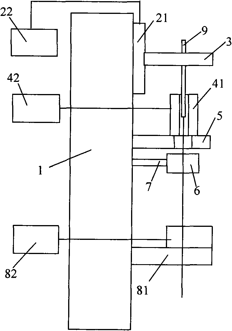
[0019] figure 2 It is a structural block diagram of the first wire drawing machine proposed by the present invention. The brushed tower base 1 is a solid and stable base, usually made of cast iron structural parts or steel structural parts. The preform rod clamping device 3 is fixed on the upper part of the tower base 1 for fixing the preform rod 9 . The base of the moving platform 21 is fixed on the tower base 1 and is located below the preform clamping device 3 , the furnace rack 5 is fixed on the bearing platform of the moving platform 21 , and the electric furnace 41 is fixed on the furnace rack 5 . The electric furnace adopts a well-type structure, with upper and lower furnace openings, and the preform is heated in the furnace. Through holes are arranged on the grate 5, and the drawn product is allowed to ...


PUM


Abstract

The invention discloses three drawbenches, which are mainly applied in the fields of precisely drawing glass tubes, glass bars, plastic tubes and plastic bars. The invention provides a drawbench, which consists of a column foot 1, a motion platform 21, a motion platform controller 22, a prefabricated bar holding device 3, an electric furnace 41, an electric furnace temperature controller 42, a grate 5, a wire diameter meter 6, a wire diameter meter frame 7, a drawing device 81, a drawing control device 82 and the like. The drawbench is characterized in that the prefabricated bar holding device 3 is fixed on the upper part of the column foot 1; the motion platform 21 is fixed on the column foot 1 and positioned below the prefabricated bar holding device 3; the grate 5 is fixed on a motion plummer of the motion platform 21; the electric furnace is fixed on the grate 5; the wire diameter meter frame 7 is fixed on the motion plummer of the motion platform 21 and positioned below the grate 5; the wire diameter meter 6 is fixed on the wire diameter meter frame 7; and the drawing device 81 is fixed on the column foot 1 and positioned below the wire diameter meter 6. The precise drawbench can improve drawing precision of a drawing system and improve utilization rate of prefabricated bars.

Description

technical field [0001] The invention relates to a wire drawing machine, which is mainly used in the field of precision drawing of glass tubes, glass rods, plastic tubes and plastic rods. Background technique [0002] Precision glass tubes, glass rods, plastic tubes and plastic rods are widely used in instrumentation, electric light source, medical equipment and communication fields. Precision glass tubes, glass rods, plastic tubes and plastic rods are usually drawn from preforms to scale by wire drawing machines. see figure 1 At present, the existing wire drawing machine consists of tower base 1, motion platform 21 and motion platform controller 22, prefabricated side clamping device 3, electric furnace 41 and electric furnace temperature controller 42, furnace frame 5, wire diameter gauge 6, wire diameter gauge Components such as frame 7, wire drawing device 81 and wire drawing control device 82 are formed. Its mechanical structure is set as follows: the moving platform ...

Claims


Application Information

Patent Timeline
Patent Type & Authority Applications(China)
IPC IPC(8): C03B23/045C03B23/047B29C55/22C03B37/025C03B37/03
Inventor 方强
Owner 方强
Why Eureka
Try Eureka