Integrally-assembled buttressed retaining wall and construction method thereof

A retaining wall and buttress-type technology, which is applied in the field of assembling integral buttress-type retaining wall structures, can solve the problems of a large amount of labor and slow construction speed, and achieve the effects of low project cost, fast construction speed and labor saving

Active Publication Date: 2010-07-28
江苏绿和环境科技有限公司
View PDF3 Cites 26 Cited by
  • Summary
  • Abstract
  • Description
  • Claims
  • Application Information

AI Technical Summary

Problems solved by technology

[0005] In order to overcome the problems that existing retaining walls require a lot of labor and slow construction speed, the technical solution of the present invention is: an assembled integral buttress-type retaining wall, comprising prefabricated concrete hollow wall panels 1, with ve...

Method used


Image

  • Integrally-assembled buttressed retaining wall and construction method thereof
  • Integrally-assembled buttressed retaining wall and construction method thereof
  • Integrally-assembled buttressed retaining wall and construction method thereof

Examples


Embodiment 1

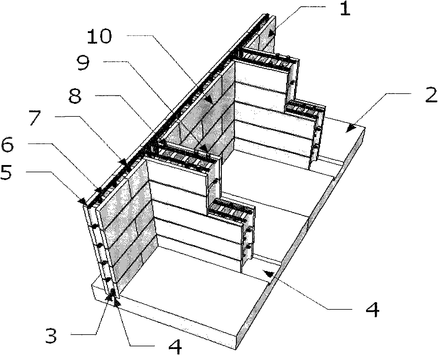
[0023] see figure 1 , an assembled monolithic buttress-type retaining wall, comprising a precast concrete hollow wall panel 1 and a prefabricated reinforced concrete bottom slab 2 with vertically lapped steel bars 3 and grooves, when assembling, the precast concrete of the lowest piece is hollow The wall panel 1 is stuck in the groove 4 and the vertical overlapping steel bar 3 is extended into the hole in the precast concrete hollow wall panel 1. In the horizontal groove of the prefabricated concrete hollow wall panel on the first floor, respectively place the horizontal stressed steel bar 5 and the L-shaped distributed steel bar 8, respectively insert the vertical stressed steel bar 7 and 9 in the holes of the wall panel and the buttress, and finally pour the hole-filled concrete An assembled integral buttress retaining wall is formed.

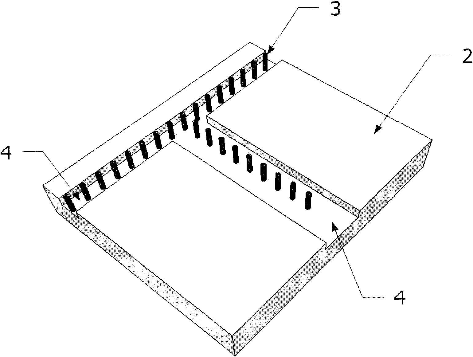
[0024] see figure 2 , the prefabricated reinforced concrete bottom slab 2 is left with vertically lapped steel bars 3 and grooves 4, the ...

Embodiment 2

[0028] Construction of assembled integral buttress retaining walls:

[0029] (a) Preparatory work: including the prefabrication preparation work of the concrete hollow wall panel 1 and the reinforced concrete floor 2 and the preparation work on the construction site. The prefabrication preparation work is carried out in the prefabrication factory. According to the design drawings, the concrete hollow wall panels 1 or hollow blocks and the reinforced concrete bottom slab 2 with vertically lapped reinforcement bars 3 and grooves 4 are prefabricated. Before the official construction on site, the site should be cleaned up, and materials (cement, sand, pebbles, graded crushed stones) should be piled up. In addition, the drainage work of the construction site should be done in advance. At the two adjacent prefabricated reinforced concrete bottom slabs 2 , the lowest prefabricated concrete hollow wall panel 1 is stuck in the grooves of the two prefabricated reinforced concrete bottom...


PUM


Abstract

The invention discloses an integrally-assembled buttressed retaining wall and a construction method thereof. The retaining wall adopts a prefabricated reinforced concrete bottom plate (2) with vertical lap-joint reinforcing steel bars (3) and grooves (4); and a wall surface plate and a buttress adopt prefabricated reinforced concrete hollow wall plates (1). When in assembling, the lowest prefabricated concrete hollow wall plate (1) is clamped in the grooves (4), and the vertical lap-joint reinforcing steel bars (3) are stretched into holes in the prefabricated concrete hollow wall plate (1) which is built in an interlaced manner; vertical and horizontal reinforcing steel bars are respectively arranged in the holes and horizontal grooves of the prefabricated concrete hollow wall plate (1); finally, concrete pouring is carried out to form the integrally-assembled buttressed retaining wall. The provided construction method of the integrally-assembled buttressed retaining wall includes the following steps in sequence: (a) preparation work; (b) foundation excavation; (c) hoisting; (d) inserting of the reinforcing steel bars and concrete pouring; (e) backfilling.

Description

technical field [0001] The invention relates to an assembled integral buttress retaining wall structure and a construction method of the retaining wall. Background technique [0002] At present, in roads, railways, and municipal projects in our country, many slope supports need to use retaining walls, and most of the retaining walls use rubble retaining walls. The rubble retaining wall requires a large amount of rubble to be mined, which destroys vegetation and is not conducive to environmental protection. Moreover, the rubble retaining wall has high requirements on the bearing capacity of the foundation, the foundation is buried deep, the amount of work is large, and the construction speed is slow. For retaining walls with relatively high soil, building rubble retaining walls can no longer make the project cost the most economical. However, various types of retaining walls poured with reinforced concrete at the construction site require a large number of formwork, and the ...

Claims


Application Information

Patent Timeline
IPC IPC(8): E02D29/02
Inventor 黄靓颜友清刘燕
Owner 江苏绿和环境科技有限公司
Why Eureka
Try Eureka