
Cable-stayed multi-layer framework structure and construction control method thereof

A multi-layer frame, cable-stayed technology, applied in the direction of structural elements, building components, building structures, etc., can solve problems such as self-weight, large additional assembly axial force, and structure burial safety.

Inactive Publication Date: 2010-07-28
WUXI RES INST OF APPLIED TECH TSINGHUA UNIV +1
View PDF6 Cites 18 Cited by
  • Summary
  • Abstract
  • Description
  • Claims
  • Application Information

AI Technical Summary

Problems solved by technology

[0004] For the cable-stayed multi-layer frame structure, if the general construction method of the traditional prestressed structure is followed, the cables need to be stretched in stages and batches during the construction process, that is, the anchor ingot structure must be built first, and then the joists and diagonals must be installed. Cables; afterward, tension the cables to make the joists form a certain anti-arch, and then install frame columns, frame beams, and floor panels on the joists layer by layer; during the process of installing the upper frame structure, due to its own weight As a result, the installed structure continues to sink, which will generate a large additional assembly axial force on the installed floor beams, burying hidden safety hazards for the structure; However, due to the huge self-weight of the structure, the tension value of the cable stays is often quite considerable, and the construction cost of the tensioning process will increase sharply

Method used


Image

  • Cable-stayed multi-layer framework structure and construction control method thereof
  • Cable-stayed multi-layer framework structure and construction control method thereof
  • Cable-stayed multi-layer framework structure and construction control method thereof

Examples


Embodiment Construction

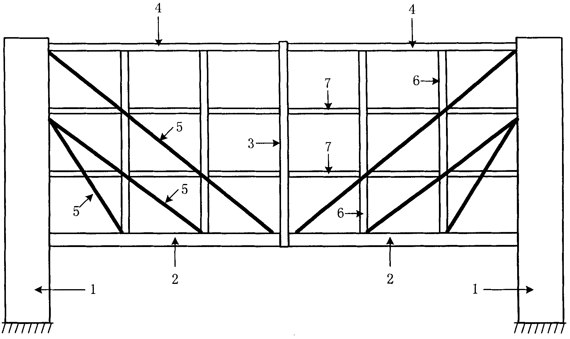
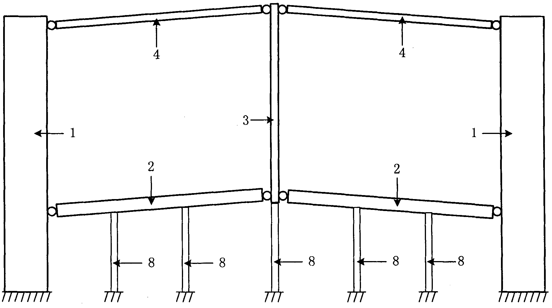
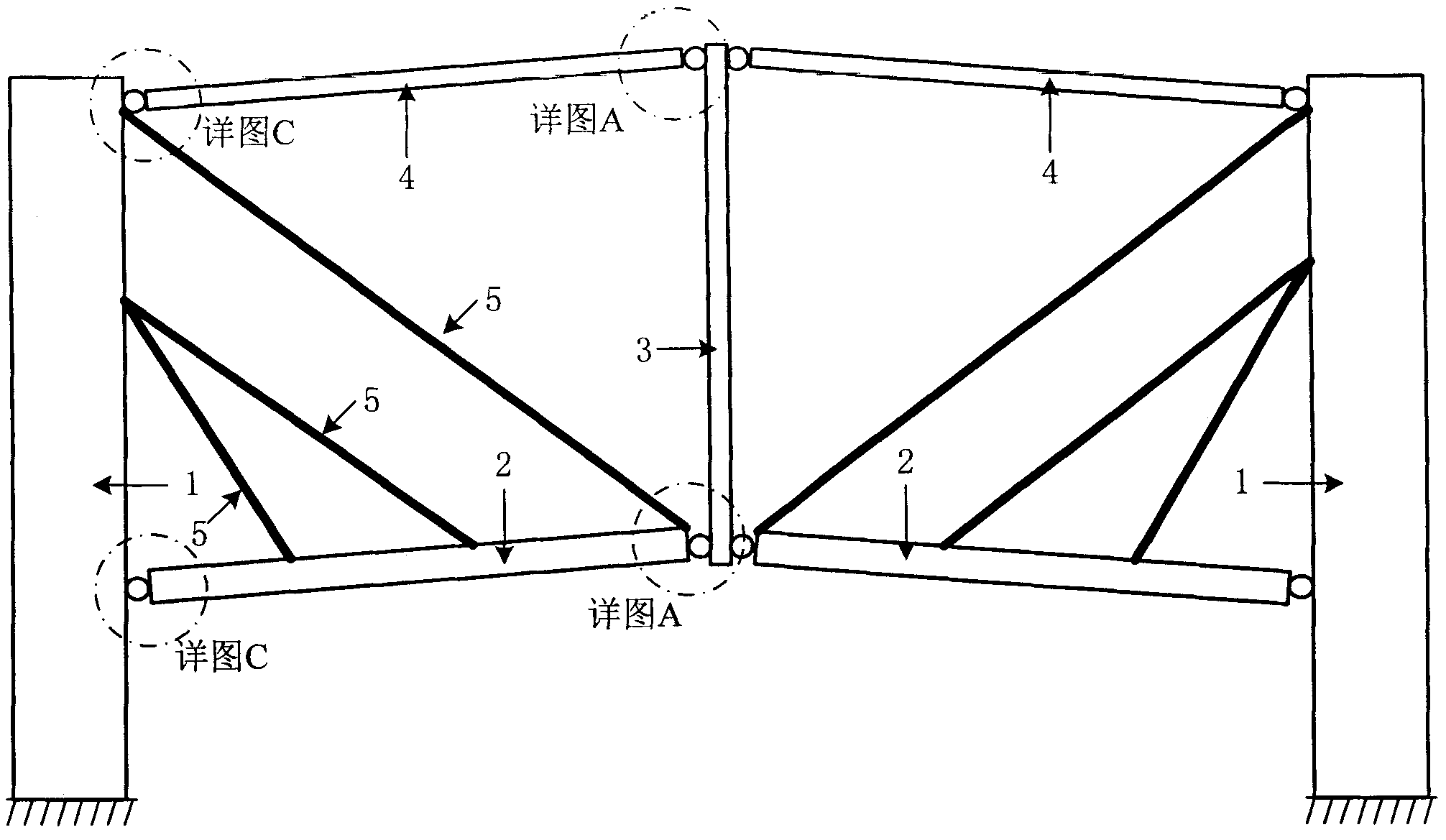
[0059] Attached below Figure 1-10 , the present invention will be described in detail.

[0060] figure 1 Middle: 1—anchor ingot structure; 2—joist beam; 3—mid-span frame column; 4—top frame beam; 5—stayed cable; 6—frame column; 7—frame beam;

[0061] figure 2 Middle: 1—anchor structure; 2—joist beam; 3—mid-span frame column; 4—top frame beam; 8—support tire frame;

[0062] image 3 Middle: 1—anchor ingot structure; 2—joist beam; 3—mid-span frame column; 4—top frame beam; 5—stayed cable;

[0063] Figure 4 Middle: 1—anchor ingot structure; 2—joist beam; 3—mid-span frame column; 4—top frame beam; 5—stayed cable; 9—first floor frame column; 10—the first floor 1st floor frame beam;

[0064] Figure 5 Middle: 1—anchor ingot structure; 2—joist beam; 3—mid-span frame column; 4—top frame beam; 5—stayed cable; 11—second floor frame column; 12—the first floor 2-story frame beam;

[0065] Figure 6 Middle: 1—anchor ingot structure; 2—joist beam; 3—mid-span frame column; 4—to...


PUM


Abstract

The invention relates to a cable-stayed multi-layer framework structure and a construction control method thereof. The method is characterized in that the construction of a cable-stayed multi-layer framework structure can be completed through specific steps, thereby avoiding cable tension. The cable-stayed multi-layer framework structure consists of an anchor structure (1), a supporting beam (2), a framework column (6), a framework beam (7), a floor panel and a stay cable (5). According to the construction control method, the supporting beam (2) is hinged with connecting joints at the two ends of the framework column (4) on the top layer during construction; the supporting beam can be lifted for a certain height above the design configuration through adjusting the length of the stay cable (5); the framework column, the framework beam and the floor panel are then arranged on the supporting beam layer by layer, and along with the increase of the building height, the supporting beam can gradually deform downwards, and tensile force can be gradually produced in the stay cable; the supporting beam is just in the horizontal position when the installation of the structure is completed; and finally the hinged joints are converted into rigid joints through the technology of converting hinged joint connection into rigid connection.

Description

technical field [0001] The invention relates to a cable-stayed multi-layer frame structure and a construction control method thereof, belonging to the technical field of structural engineering. technical background [0002] In modern multi-storey and high-rise buildings, it is often desired to create a column-free and transparent large space on the ground floor or some middle floors. If the traditional frame structure is used to meet this demand, it will inevitably cause the size of some components to be too large; when the span is large, it is difficult to meet the requirements simply by bending the frame beam to bear the load of the superstructure. In space structure and bridge engineering, in order to achieve large spans, prestressed structures are often used, such as long-span public buildings such as space roofs, and bridge structures such as cable-stayed bridges and suspension bridges. It is rarely used in frame structures. For this reason, the concept of prestressed...

Claims


Application Information

Patent Timeline
IPC IPC(8): E04B1/19E04C5/12E04G21/00
Inventor 郭彦林王小安田广宇窦超王昆
Owner WUXI RES INST OF APPLIED TECH TSINGHUA UNIV
Learn More