Multispectral uniform surface light source

A multi-spectral, surface light source technology, applied in the direction of light source, electric light source, point light source, etc., can solve the problems of unable to realize spectral responsivity detection, complicated processing of curved reflector, affecting the accuracy of camera measurement, etc., to achieve multi-spectral Color mixing, light weight, easy installation effect

Inactive Publication Date: 2010-07-28
BEIJING INSTITUTE OF TECHNOLOGYGY
View PDF8 Cites 14 Cited by
  • Summary
  • Abstract
  • Description
  • Claims
  • Application Information

AI Technical Summary

Problems solved by technology

Patent 200810104199.7 uses a diffuser plate and a curved reflector to form a surface light source, which has good stability, safety and reliability, but the processing of the curved reflector is complicated, and the thickness of the surface light source is relatively large
Another type of LED surface light source does not require light guide plates or reflectors due to the use of LED array lighting. For example, patent CN201057435Y uses an adjustable constant current source to drive the LED array to provide a uniform surface light source with small size, high uniformity, and low heat dissipation. However, the device does not have multi-spectral characteristics and cannot realize multiple spectral responsivity detection
In the patent CN2852594Y, multiple colors of LEDs are used to form an LED array, providing a surface light source with variable color tone, but the PWM driving method used will cause the LED array to produce high-frequency flicker, which cannot be detected by human eyes , but it will cause the instability of the photo brightness of the camera under test, which will affect the measurement accuracy of the camera

Method used


Image

  • Multispectral uniform surface light source
  • Multispectral uniform surface light source
  • Multispectral uniform surface light source

Examples


Embodiment

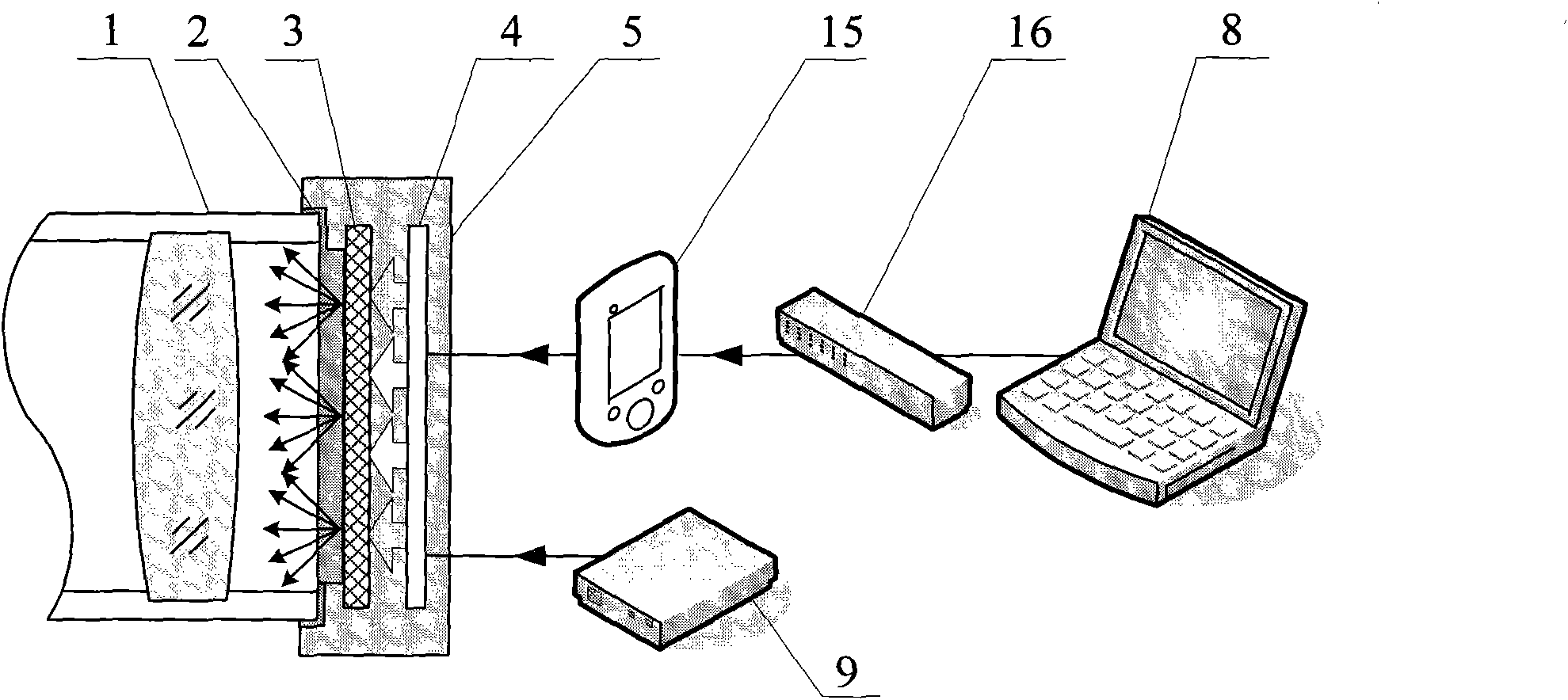
[0042] This embodiment is aimed at the multi-spectral uniform surface light source of the camera under test with a clear aperture of 150mm, which can generate uniform light-emitting surfaces with four spectrums of red, green, blue and near-infrared.

[0043] like image 3 As shown, the multi-spectral uniform surface light source includes a card mounting interface 2, a uniform light system 3, a multi-spectral light source circuit board 4, a casing 5, 15-industrial control human-machine interface, a switch 16, a computer 8, and a power supply 9.

[0044] in:

[0045] The clamping interface 2 is connected with the casing 5, and its inner dimension is the same as the outer dimension of the light inlet 1 of the object under test, so that the entire surface light source can be fixed on the light inlet 1 of the object under test.

[0046] The uniform light system 3 is installed on the light outlet of the casing 5 and is located between the light inlet 1 of the object under test and th...


PUM


Abstract

The invention relates to a multispectral uniform surface light source for generating a multispectral uniform light-emitting surface and suitable for detecting the image surface uniformity and the spectral response of photoelectronic imaging equipment, i.e. a camera and the like, belonging to the technical field of optical precision measurement. The multispectral uniform surface light source comprises a shell, a light source controller, a light source driver, a light balancing system and a multispectral light-emitting diode (LED) array, wherein the light source controller and the light source driver are fixed in the shell; the light balancing system is fixed on a light-emitting opening of the shell; the multispectral LED array is fixed in the shell, and multispectral light rays emitted by the multispectral LED array are emitted out of the light-emitting opening of the shell after penetrating through the light balancing system; a light balancing plate scatters the light rays emitted by the multispectral LED array to generate a multispectral uniform lambert surface, and the illumination of the lambert surface can be regulated. The light source has high brightness and small volume and can realize the spectral turning flashing and the multispectral colour mixing and meet the requirements of the fast detection and calibration of the image surface uniformity and the dynamic spectral response of a photoelectronic imaging system.

Description

technical field [0001] The invention belongs to the technical field of optical imaging testing, can be used to generate a multi-spectrum uniform light-emitting surface, and is mainly applicable to the image surface uniformity and spectral response detection of photoelectric imaging equipment such as cameras. technical background [0002] The optoelectronic imaging system in the field of aerospace science and technology industry has developed rapidly, and many new imaging satellite platforms have added high-performance optoelectronic imaging systems. As the "eyes" of satellites, optoelectronic equipment has become an important payload on satellites, mainly used to realize the functions of observation and mapping of ground targets. [0003] The core component in the photoelectric imaging system - high-precision CCD image sensor is composed of discrete photosensitive picture elements. Although the geometrical precision of modern sensors is very high, the responsivity of each p...

Claims


Application Information

Patent Timeline
Patent Type & Authority Applications(China)
IPC IPC(8): F21S8/00F21V15/02F21V5/08F21V9/00F21V23/00F21Y101/02
Inventor 赵维谦胡永力张慧孙若端郭俊杰乔茂勇孙佳沙定国
Owner BEIJING INSTITUTE OF TECHNOLOGYGY
Why Eureka
Try Eureka