Pipe joint structure

A pipe joint and pipe turning technology, which is applied in the field of pipe joint structure of heat exchangers, can solve the problems of cost and weight increase, high processing cost, and more materials, and achieve the effects of weight reduction, welding strength increase, and cost reduction

Inactive Publication Date: 2010-07-28
SANHUA HLDG GRP +1
View PDF0 Cites 18 Cited by
  • Summary
  • Abstract
  • Description
  • Claims
  • Application Information

AI Technical Summary

Problems solved by technology

That is, in the structure of the pipe joint, since the aluminum block is formed by extruding and then drilling, or is formed by all machining, there are many problems of material consumption and high processing cost, which leads to the product cost and weight increase

Method used


Image

  • Pipe joint structure
  • Pipe joint structure
  • Pipe joint structure

Examples


Embodiment Construction

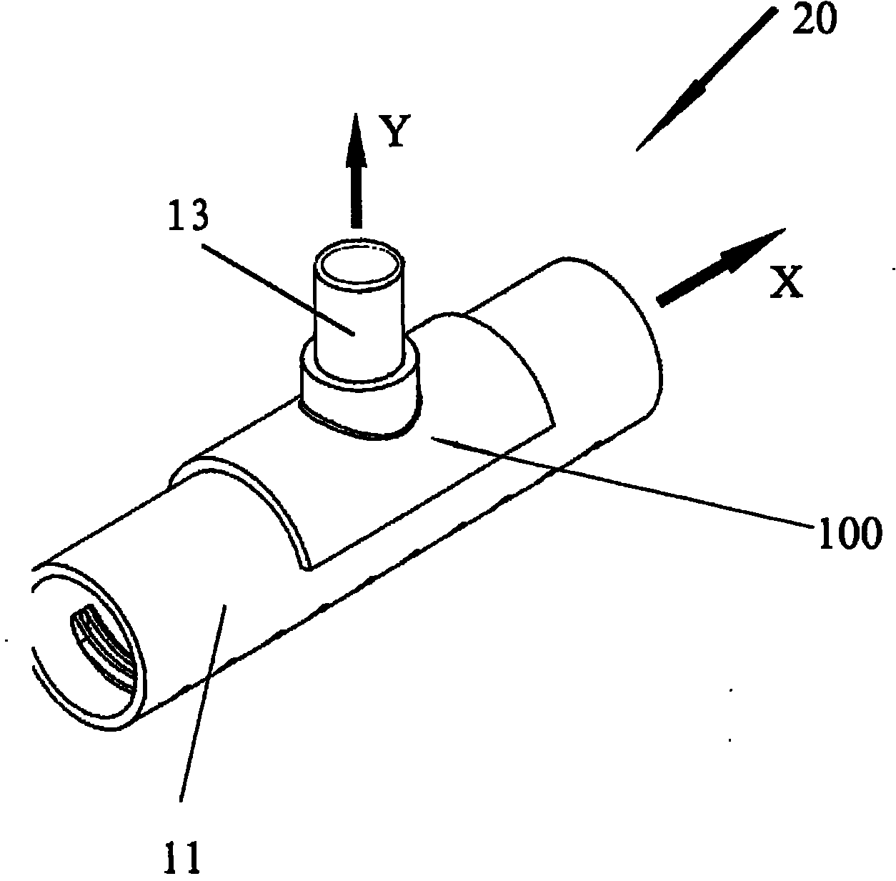
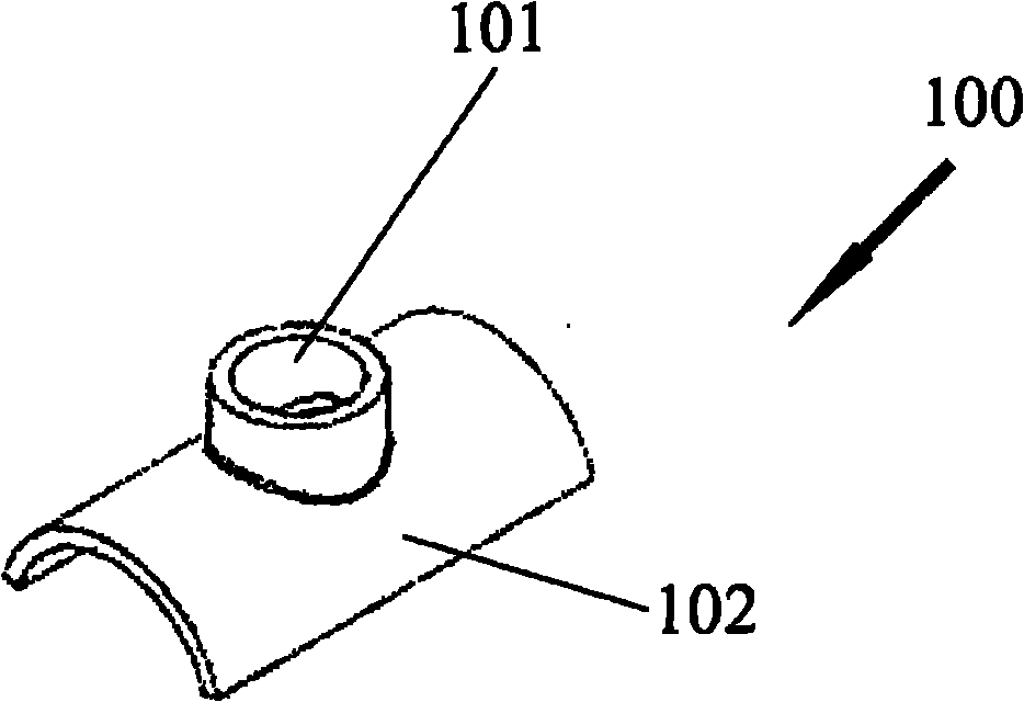
[0029] figure 2 is a perspective view of the pipe joint structure 20 according to the first embodiment of the present invention. The pipe joint structure 20 includes a manifold 11, an inlet and outlet pipe 13 and a pipe joint 100, wherein the manifold 11 is along a first direction (such as figure 2 The x-direction shown in ) transport fluid, the fluid includes but not limited to heat exchange medium such as water, oil, the header 11 has a through hole (not shown) formed in its side wall for Transversely communicate with other pipelines; the inlet and outlet pipes 13 are along the second direction (such as figure 2 The y direction shown in ) transports fluid, usually the first direction is substantially perpendicular to the second direction; the pipe joint 100 is used to sealably engage with the header 11 and the inlet and outlet pipes 13, the pipe joint 100 is hollow, and can It includes a first joint portion 101 that is jointed with one end of the inlet and outlet pipe 1...


PUM


Abstract

The invention relates to a pipe joint structure, comprising a collecting pipe for delivering fluid along a first direction, an inlet/outlet pipe for delivering fluid along a second direction which is perpendicular to the first direction and a hollow pipe joint hermetically jointed to the collecting pipe and the inlet/outlet pipe. The first joint part of the pipe joint is jointed to one end part of the inlet/outlet pipe and maintains the fluid communication, the second joint part of the pipe joint is jointed to the collecting pipe and maintains the fluid communication with the collecting pie via a hole on the side wall of the collecting pipe, thereby enabling the fluid communication between the inlet/outlet pipe and the collecting pipe is maintained. The second joint part forms a pipe-like wall or partially pipe-like wall configuration jointed to the collecting pipe. The pipe joint structure has advantages of small pressure drop in the inlet/outlet pipe, high burst strength in the joint part and low cost.

Description

technical field [0001] The present invention relates to a pipe joint structure, in particular but not exclusively to a pipe joint structure for a heat exchanger. Background technique [0002] In the application of various pipeline systems, in order to realize the change of pipeline conveying direction, the diversion of fluid, the connection between various pipelines, etc., it is inevitable to use the pipe joint structure, especially for the connection between two vertical pipelines. Connection. For example, in the existing aluminum heat exchanger, the method of directly inserting the inlet and outlet pipes as the branch pipes into the header pipe as the main pipe is usually adopted to realize the fluid communication between the two pipes. [0003] figure 1 A prior art fitting structure 10 is shown. The pipe joint structure 10 includes a header 11 for conveying refrigerant such as water in the vertical direction, a hole 12 on the side wall of the header, and an inlet and o...

Claims


Application Information

Patent Timeline
Patent Type & Authority Applications(China)
IPC IPC(8): F28F9/26F28F9/02
Inventor 汪峰葛好德黄宁杰
Owner SANHUA HLDG GRP
Why Eureka
Try Eureka