Method for determining separation and distribution of structural-member composite crack front stress intensity factors

A stress intensity factor, crack front technology, applied in the field of structural safety analysis and assessment, can solve problems such as low calculation efficiency, poor mathematical simulation effect, and low accuracy

Inactive Publication Date: 2010-07-28
ZHEJIANG UNIV OF TECH
View PDF1 Cites 14 Cited by
  • Summary
  • Abstract
  • Description
  • Claims
  • Application Information

AI Technical Summary

Problems solved by technology

[0007] In order to overcome the low calculation efficiency, poor mathematical simulation effect and low accuracy of the existing method for determining the stress intensity factor distribution of the crack front of structural parts, and it is not suitable for complex loads where cracks are combined in types I, II and III K of the lower crack front I 、K II and K III The separation and their distribution calculation along the crack front, etc., the present invention provides a method for determining the separation and distribution of the stress intensity factors of the composite crack front of structural parts, and can perform the curved three-dimensional crack front with high precision and high efficiency. The stress intensity factor K I 、K II and K III The separation and determination of their distribution along the crack front; and the calculation efficiency is high, the mathematical simulation effect is good, and the precision is high

Method used


Image

  • Method for determining separation and distribution of structural-member composite crack front stress intensity factors
  • Method for determining separation and distribution of structural-member composite crack front stress intensity factors
  • Method for determining separation and distribution of structural-member composite crack front stress intensity factors

Examples


Embodiment 1

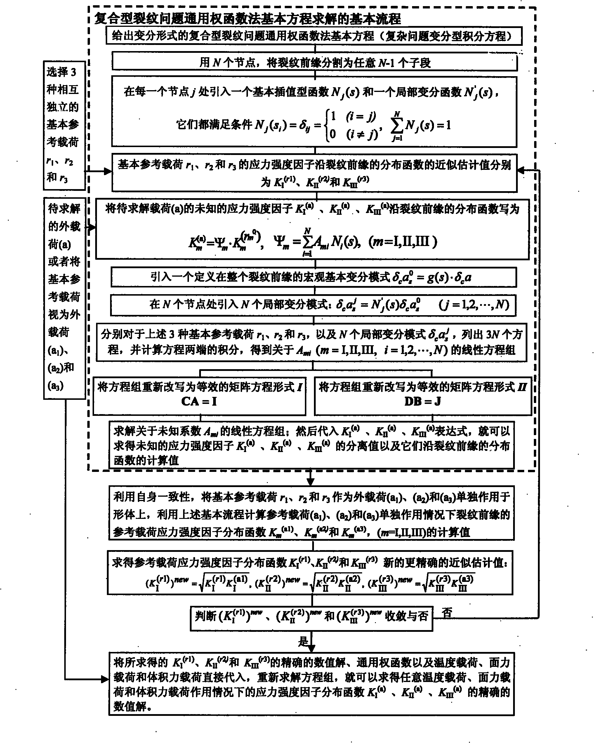
[0105] refer to figure 1 , Figure 4 , Figure 5 , Figure 6 , Figure 7 , a method for determining the separation and distribution of stress intensity factors at the front edge of composite cracks in structural parts, the method mainly includes the following steps (see attached figure 1 ):

[0106] 1), give the thermal load, surface force load and body force load borne by the structural member, and the three-dimensional I, II, III expressed in the form of variational integral equation under the action of the three loads alone or together The basic equation of the universal weight function method for the complex crack problem (complex problem variational integral equation), as shown in formula (1);

[0107] 2) Use N nodes to divide the crack front into any N-1 sub-segments, and introduce a basic interpolation function N at each node j j (s) and a local variational function N′ j (s), they all satisfy conditional formula (2);

[0108] 3) Select three independent basic re...

Embodiment 2

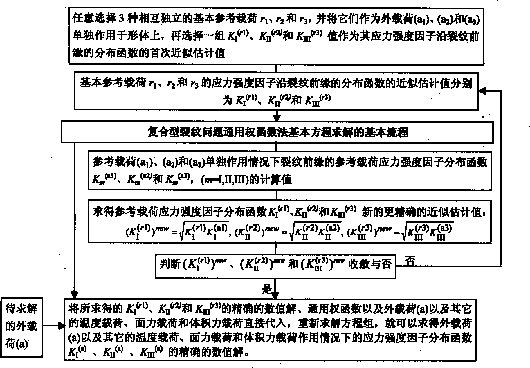
[0120] refer to figure 1 , figure 2 , Figure 4 , Figure 5 , Figure 6 , Figure 7 , Figure 8 , according to the method for determining the separation and distribution of the stress intensity factors of the composite crack front of the structural part described in Example 1, the crack front stress intensity of the semi-elliptical surface crack in the Z-direction fixed plate at both ends under the action of three kinds of crack surface forces Factor K I 、K II and K III Separation and its distribution, according to figure 2 The first execution method (high precision execution mode) shown is determined. Figure 8 Represents a semi-elliptical surface crack with a depth ratio of a / T=0.5 and a shape ratio of a / c=0.5, with uniform pressure distribution on the upper and lower crack surfaces, uniform shear force on the crack surface in the X direction, and uniform shear force on the crack surface in the Y direction. Under load, the stress intensity factor K at the crack f...

Embodiment 3

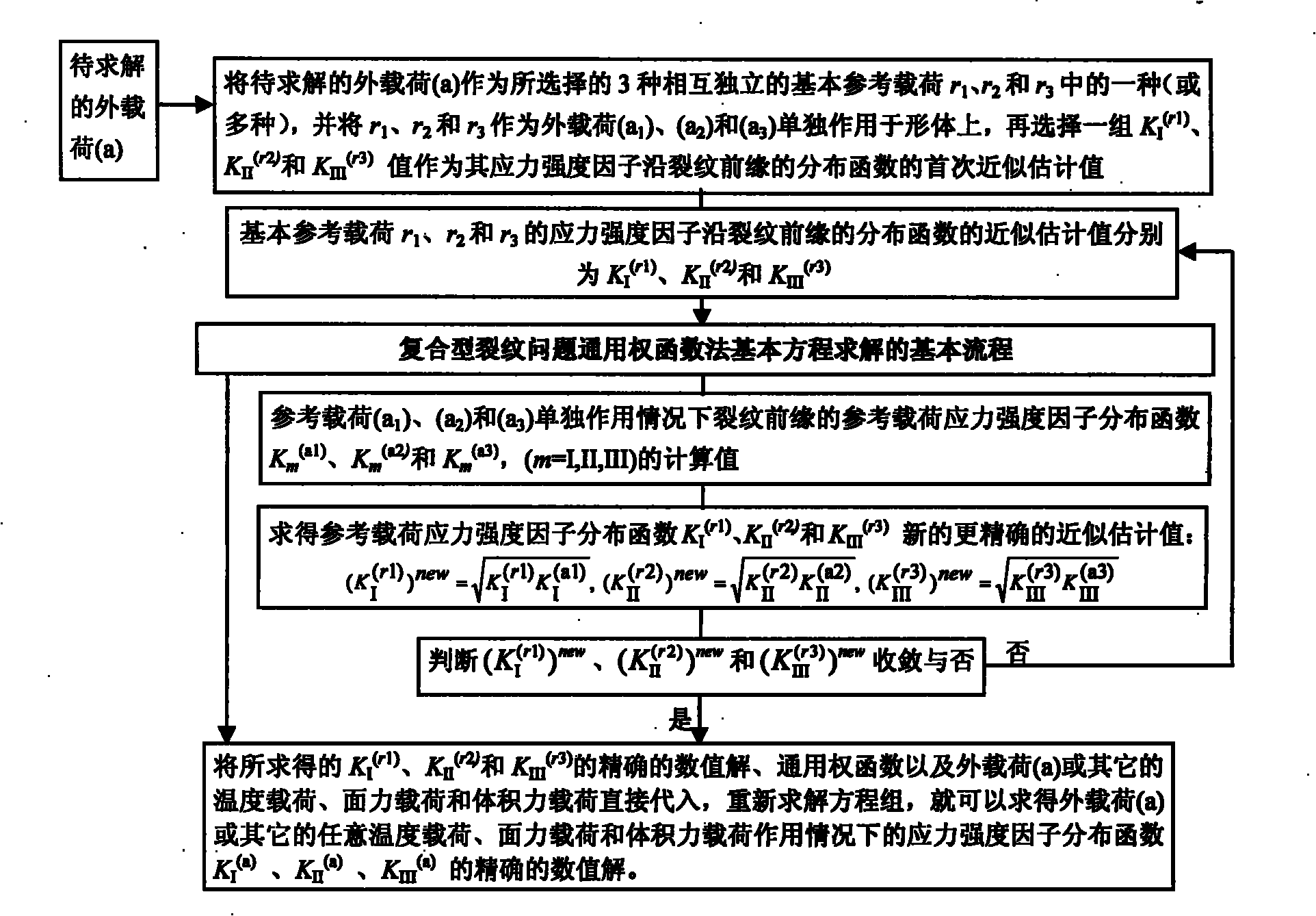
[0122] refer to figure 1 , image 3 , Figure 4 , Figure 5 , Figure 6 , Figure 7 , Figure 9 , according to the method for determining the separation and distribution of stress intensity factors at the front edge of composite cracks in structural parts described in Example 1, for cracks on the semi-elliptical surface of a fixed plate in the Z direction at both ends under several plate surface pressures and temperature loads, the crack front edge stress intensity factor K I 、K II and K III Separation and its distribution, according to image 3 The second execution method (high-efficiency execution mode) shown is determined. Figure 9 Indicates the semi-elliptical surface crack with depth ratio a / T=0.5, shape ratio a / c=0.5, uniform pressure on the front surface of the plate, staggered uniform pressure on the front surface of the plate, uniform pressure on the upper half of the plate surface and uniform temperature drop of the whole plate Under the four loading condi...


PUM


Abstract

The invention relates to a method determining separation and distribution of structural-member composite crack front stress intensity factors. The method comprises the following steps: giving thermal load, surface force load and volume force load borne by a structural member, and a universal weighting function method basic equation for three-dimensional I, II, III composite crack problems under the independent or combined actions of the thermal load, the surface force load and the volume force load; dividing the crack front into random N-1 numbered subsections through N numbered nodes, and introducing a basic interpolation function Nj(s) and a partial variation function N'j(s) at each node j, thereby constructing a finite number of partial variation modes and interpolation modes; and then introducing 3 basic reference loads to solve the basic equation, thereby determining the numerical solution of the separation and distribution of composite stress intensity factors KI, KII and KIII. By utilizing the self consistency, the method can obtain the high-precision exact solution of the distribution of the three-dimensional crack front composite stress intensity factors KI, KII and KIII by constructing an iterative process.

Description

technical field [0001] The invention relates to the field of structural safety analysis and evaluation, in particular to the stress intensity factor K at the leading edge of a composite crack in a structural part I 、K II and K III The method of determination of the separation of cracks and their distribution along the crack front and the design of computer calculation programs. It is used to determine the stress intensity factor K of the three-dimensional compound crack front in structural parts with high precision and high efficiency in the process of structural safety assessment I 、K II and K III separation and their distribution along the crack front. [0002] When the stress intensity factor K I 、K II and K III After the distribution of is determined, the direction of crack propagation under the external load can be determined, and compared with the fracture toughness Kc of the material, the safety of the structural member can be determined; or, the safety of the s...

Claims


Application Information

Patent Timeline
Patent Type & Authority Applications(China)
IPC IPC(8): G01N3/08G06F19/00
Inventor 卢炎麟
Owner ZHEJIANG UNIV OF TECH
Why Eureka
Try Eureka