Magnetoelectric loop wire test method for continuously applying scanning magnetic field and device thereof

A test device, magnetoelectric technology, applied in the direction of hysteresis curve measurement, magnetic performance measurement, etc., can solve the problem of slow test speed, and achieve the effect of fast measurement, simple operation and high degree of automation

Inactive Publication Date: 2010-07-28
XIAMEN UNIV
View PDF1 Cites 12 Cited by
  • Summary
  • Abstract
  • Description
  • Claims
  • Application Information

AI Technical Summary

Problems solved by technology

[0009] The object of the present invention is to provide a magnetoelectric loop testing device that con

Method used


Image

  • Magnetoelectric loop wire test method for continuously applying scanning magnetic field and device thereof
  • Magnetoelectric loop wire test method for continuously applying scanning magnetic field and device thereof
  • Magnetoelectric loop wire test method for continuously applying scanning magnetic field and device thereof

Examples


Embodiment Construction

[0070] The following embodiments will further illustrate the present invention in conjunction with the accompanying drawings.

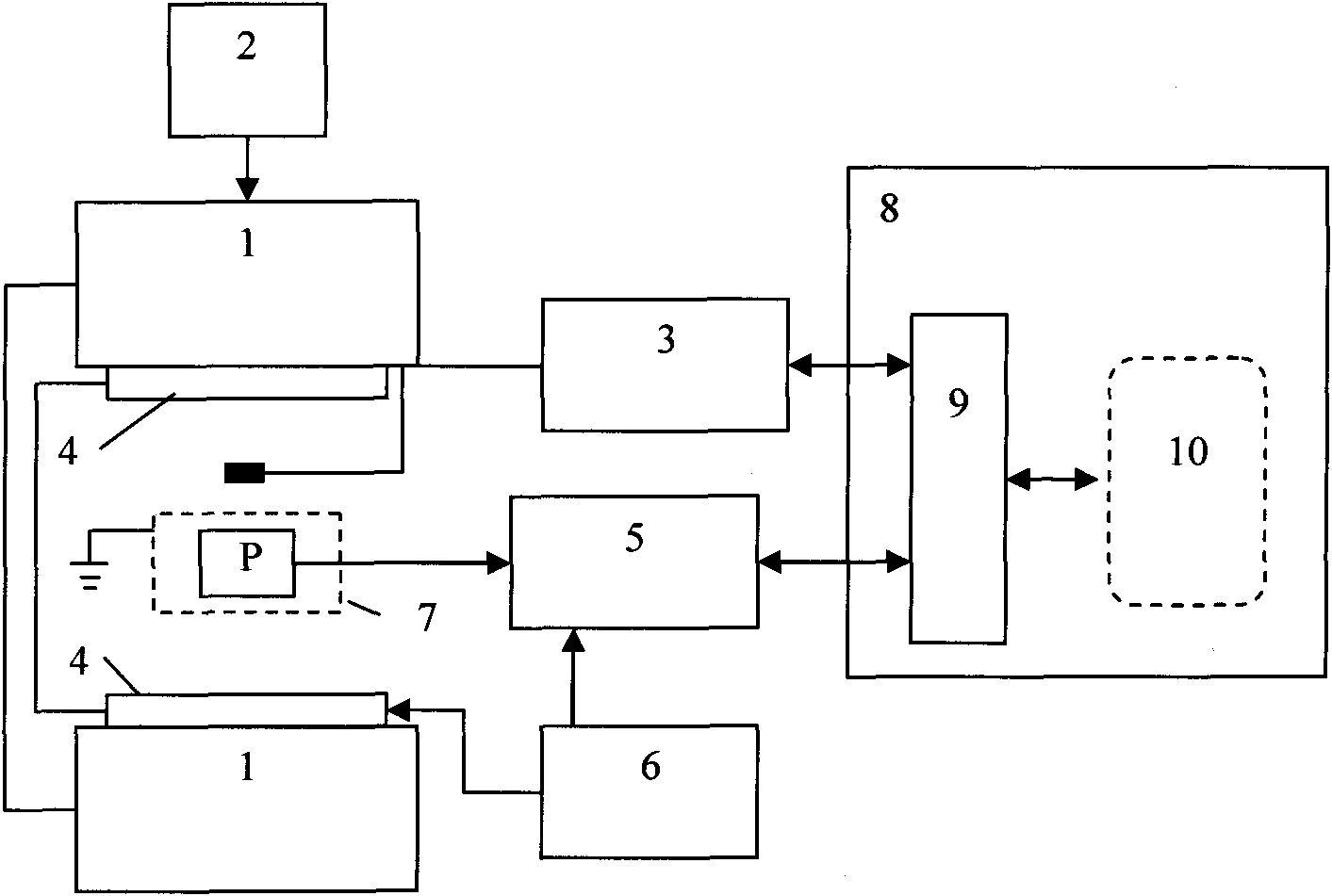
[0071] according to figure 1 The test device is connected in the same way, and an electromagnet 1 (model U-85) is driven by a DC power supply 2 (model U85D). The magnetic field intensity generated by the electromagnet 1 is measured by a Tesla meter 3 (model YL1020) with a communication port, and the Hall probe of the Tesla meter 3 is placed in the uniform strength area of ​​the electromagnet 1. The Helmertz coil 4 is placed in the electromagnet 1, and the center of the uniform intensity area of ​​the coil coincides with the center of the uniform intensity area of ​​the electromagnet. The sample P is placed in the center of the uniform intensity area, surrounded by a grounded shield 7 . The voltage output terminal of the function signal generator 6 (model DG2012A) is connected to the Helmertz coil 4, and outputs an AC voltage with a frequency from 1 ...


PUM


Abstract

The invention discloses a magnetoelectric loop wire test method for continuously applying a scanning magnetic field and a device thereof and relates to a performance test method of a magnetoelectric material and a test device thereof. The device is provided with an electromagnet, a direct current power source, a teslameter, a Helmholtz coil, a phase-locked amplifier, a function signal generator, a shield and a computer. The magnetoelectric loop wire test method comprises the following steps: connecting a sample with the input end of the phase-locked amplifier, setting the frequency of the function signal generator and a time function of the phase-locked amplifier and starting signal processing software; controlling the electromagnet to output the scanning magnetic filed and applying the scanning magnetic field on the sample; continuously acquiring the amplitude and the phase of magnetoelectric voltage as well as a magnetic field intensity value of the scanning magnetic field by the computer; carrying out signal processing on the acquired amplitude and phase and automatically setting signs of the amplitude to obtain the magnetoelectric voltage by the computer according to the rule that the magnetoelectric voltage is positive when the phase is less than or equal to zero and is negative when the phase is more than zero; and automatically producing a magnetoelectric loop in real time and saving experimental data by taking the magnetic field intensity value of the scanning magnetic field as an X axle and the magnetoelectric voltage as a Y axle through the computer.

Description

technical field [0001] The invention relates to a performance testing method and a testing device for a magnetoelectric material, in particular to a magnetoelectric loop testing method and a device for continuously applying a scanning magnetic field. Background technique [0002] The magnetoelectric effect is the mutual coupling effect of the magnetic field and the electric field. The effect of the electric polarization induced by the magnetic field is the positive magnetoelectric effect, which is usually referred to as the magnetoelectric effect. In addition, there is also the inverse magnetoelectric effect of the electric field induced magnetic polarization. Materials with magnetoelectric effects are collectively called magnetoelectric materials, which have broad application prospects in the fields of sensors, actuators, memories, etc., and are a new type of multifunctional information materials. [0003] The magnetoelectric effect is generally measured by applying a magne...

Claims


Application Information

Patent Timeline
IPC IPC(8): G01R33/14
Inventor 施展曾德武金大军张锦彬马云庆黄艺雄王翠萍刘兴军
Owner XIAMEN UNIV
Why Eureka
Try Eureka