Valve mechanism of switch cabinet

A technology for switch cabinets and valves, which is applied in the direction of pull-out switch cabinets, switch devices, guard plates/protection devices of switch devices, etc., and can solve the problem of reduced service life of switch cabinet valve mechanisms, reduced service life of ropes, and increased rope loads, etc. problems, to achieve the effect of improving the service life, reducing the rope load and preventing safety accidents

Active Publication Date: 2010-07-28
HUAYI ELECTRIC CO LTD
View PDF5 Cites 19 Cited by
  • Summary
  • Abstract
  • Description
  • Claims
  • Application Information

AI Technical Summary

Problems solved by technology

[0003] For this reason, the technical problem to be solved by the present invention is that the counterweight for realizing the closing of the upper and lower valves arranged on the switch cabinet valve mechanism in the prior art increases the load of the rope, which leads to a reduction in the service life of the rope, thereby causing the switch cabinet to be closed. The service life of the valve mechanism is reduced, and a switch cabinet valve mechanism with a long life is provided

Method used


Image

  • Valve mechanism of switch cabinet
  • Valve mechanism of switch cabinet
  • Valve mechanism of switch cabinet

Examples


Embodiment Construction

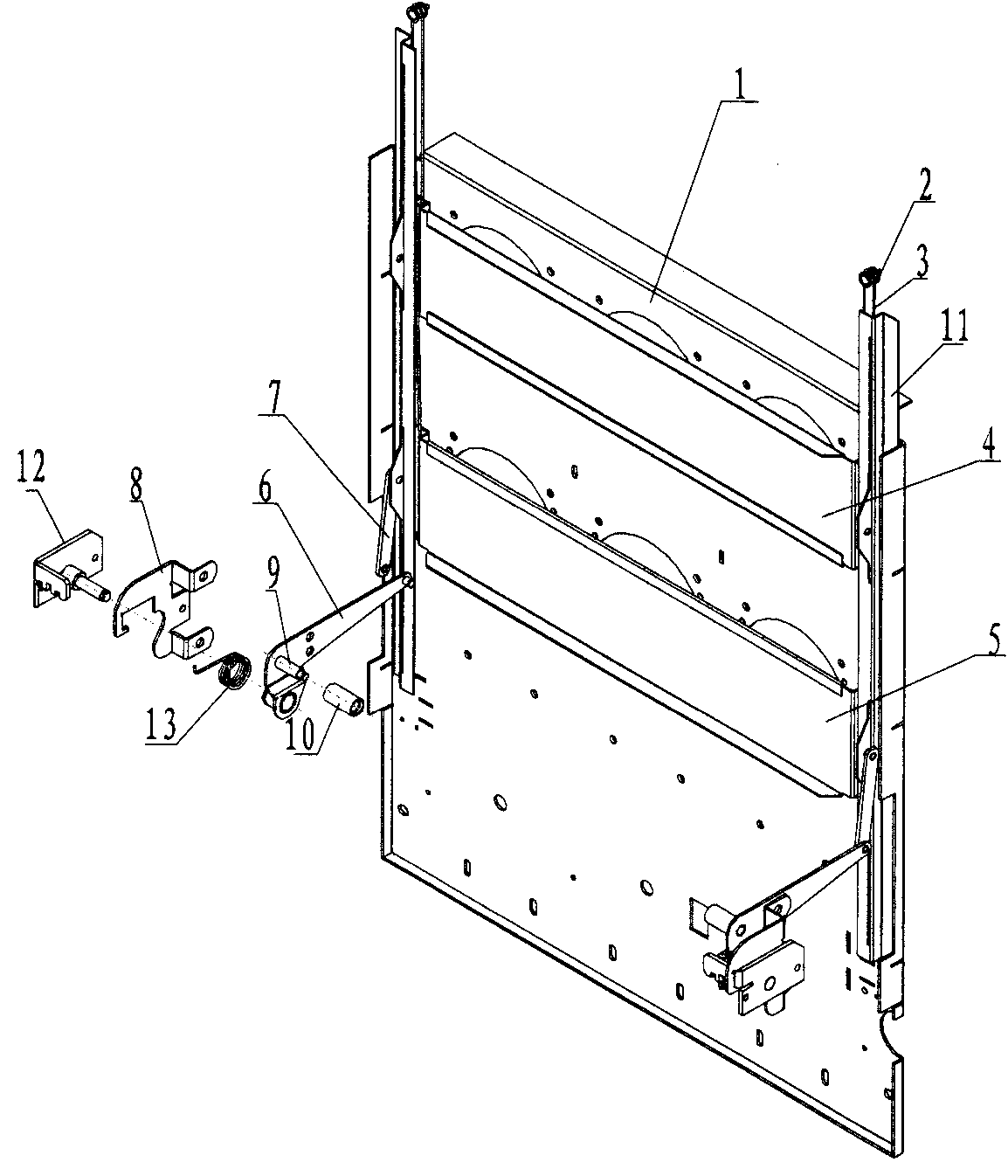
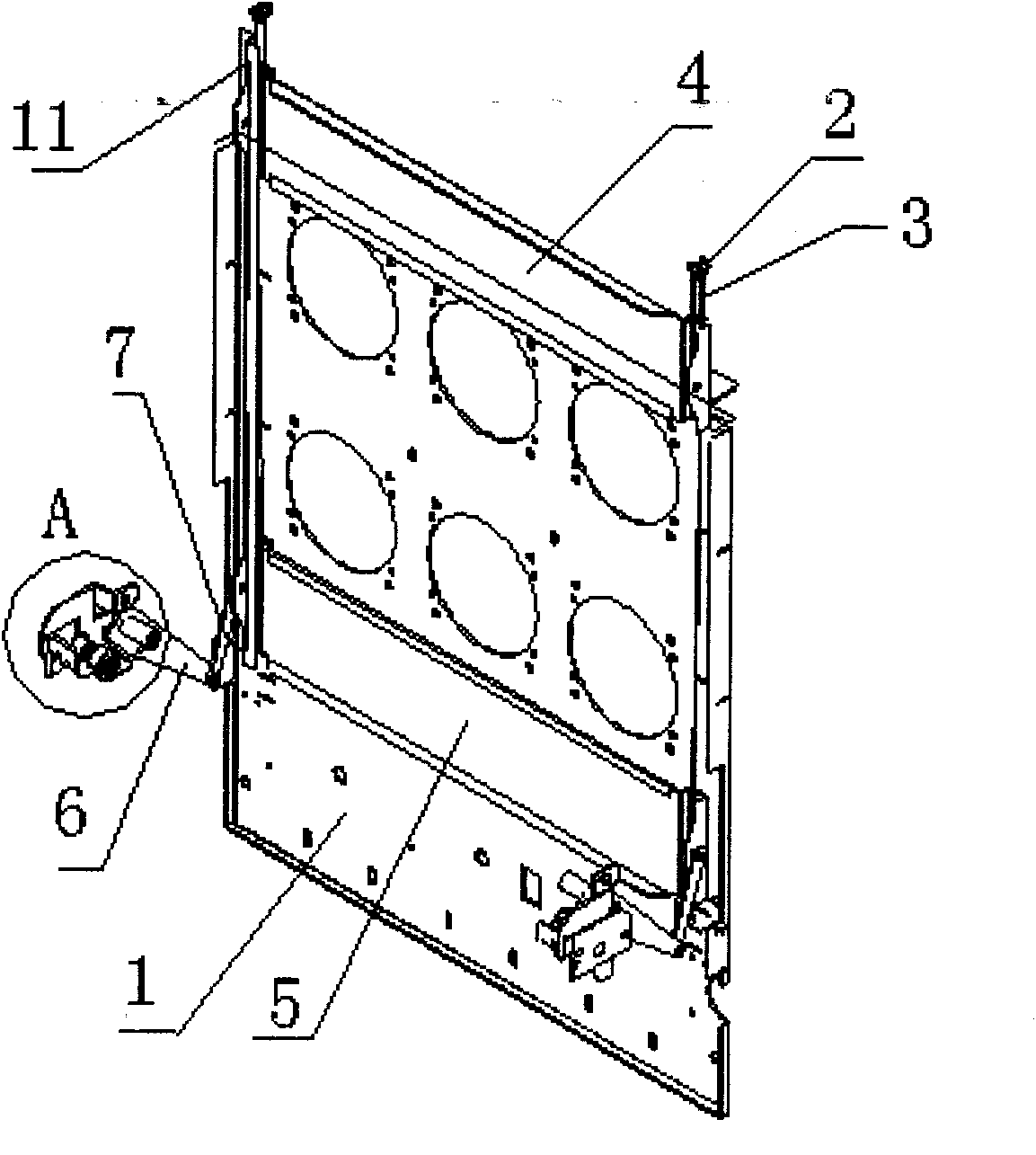
[0031] Such as Figure 1 to Figure 4 As shown, a switchgear valve mechanism of this embodiment includes a middle partition 1, and upper and lower contact box holes are formed on the middle partition 1;

[0032] Fixed pulley 2, the fixed pulley 2 is provided with two, respectively fixed on the cabinet above the left and right sides of the middle partition 1;

[0033] Rope 3, said rope 3 is provided with two, respectively wound on the corresponding said fixed pulley 2;

[0034] Upper and lower valves, one end of the same side of the upper valve 4 and the lower valve 5 is respectively arranged on the two ends of the same side of the rope 3, and the upper valve 4 and the lower valve 5 are wound on the fixed pulley The up and down movement of the rope 3 on the 2 drives the movement of the upper valve 4 and the lower valve 5 so as to realize the opening and closing of the upper and lower contact box holes;

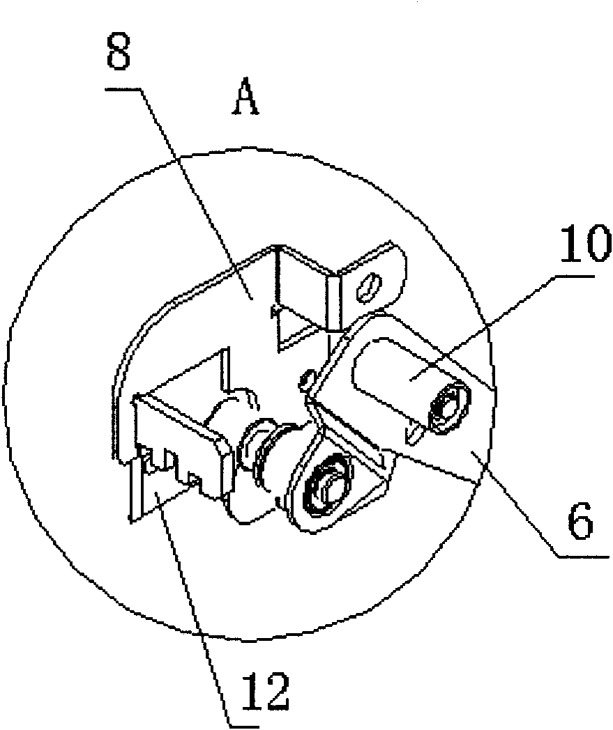
[0035] The lower valve operating mechanism, the lower valve operating mec...


PUM


Abstract

The invention relates to a valve mechanism of a switch cabinet, comprising a middle clapboard, fixed pulleys, ropes, upper and lower valves and lower valve operating mechanisms which are fixedly arranged on cabinets at the left and right sides of the middle clapboard and are connected with the lower valve, wherein each lower valve operating mechanism comprises a master connecting rod with one end rotatably arranged on the cabinet at the left or right side of the middle clapboard, a resetting device which is arranged between the cabinet and the master connecting rod and realizes resetting of the master connecting rod driven by external force to rotate, a handcart force applied portion which is arranged on the master connecting rod and is used for a push board of the handcart to apply force to the master connecting rod so as to drive the master connecting rod to rotate, and a slave connecting rod with one end hinged with one end of the lower valve at the same side and the other end hinged with the other end of the master connecting rod; and driven by the master connecting rod, the slave connecting rod drives the lower valve to move up and down. The valve mechanism has simple structure, long service life and good synchronicity.

Description

technical field [0001] The invention relates to a shutter mechanism of a switchgear, in particular to a shutter mechanism that can be automatically opened or closed when a handcart is pushed in or pulled out. Background technique [0002] The shutter mechanism is an integral part of removable AC metal-enclosed switchgear and control equipment, and has two switchable positions. In the open position, it allows the moving contacts of the removable part to engage with the live static contacts. In the closed position it becomes part of the bulkhead or housing covering the stationary contacts. The switchgear valve mechanism in the prior art has connecting rod transmission, chain connecting rod transmission and gear connecting rod transmission, etc. in the transmission modes for realizing the opening or closing of the upper and lower valves. Chinese patent document CN2773954Y proposes a pulley for high-voltage switchgear valves. The transmission mechanism consists of the guide pl...

Claims


Application Information

Patent Timeline
Patent Type & Authority Applications(China)
IPC IPC(8): H02B11/24H02B11/133
Inventor 徐根安杨丁丁黄洋陈钢吴士敏
Owner HUAYI ELECTRIC CO LTD
Why Eureka
Try Eureka