Light-emitting diode street lamp energy-saving automatic control method and device

An automatic control device, LED street lamp technology, applied in the direction of energy-saving control technology, lighting device, energy-saving lighting, etc., can solve the problems of prolonging the working life of LED street lamps, poor road lighting quality, and high manufacturing cost, so as to improve road lighting. The effect of quality, improved service life and convenient manufacturing

Inactive Publication Date: 2010-07-28
王春
View PDF5 Cites 6 Cited by
  • Summary
  • Abstract
  • Description
  • Claims
  • Application Information

AI Technical Summary

Problems solved by technology

These two LED street lamp energy-saving automatic control methods and devices have the following disadvantages: 1. The former only solves the energy-saving problem of LED street lamps, but does not solve the problem of prolonging the working life of LED street lamps; 2. The latter solves the energy-saving problem of LED street lamps, It also solves the problem of prolonging its working life, but its structure is complicated. Two lamps need to be arranged on one lampshade, and two LED light source chips are needed. The manufacturing cost is high, and the installation is also inconvenient, and the reliability is also poor; followed by road lighting Poor quality, when one light is on and the other is off, there are dark shadows in the brightness of the road lighting

Method used


Image

  • Light-emitting diode street lamp energy-saving automatic control method and device
  • Light-emitting diode street lamp energy-saving automatic control method and device
  • Light-emitting diode street lamp energy-saving automatic control method and device

Examples


Embodiment Construction

[0017] The technical solution of the present invention will be described in detail below in conjunction with the accompanying drawings and embodiments.

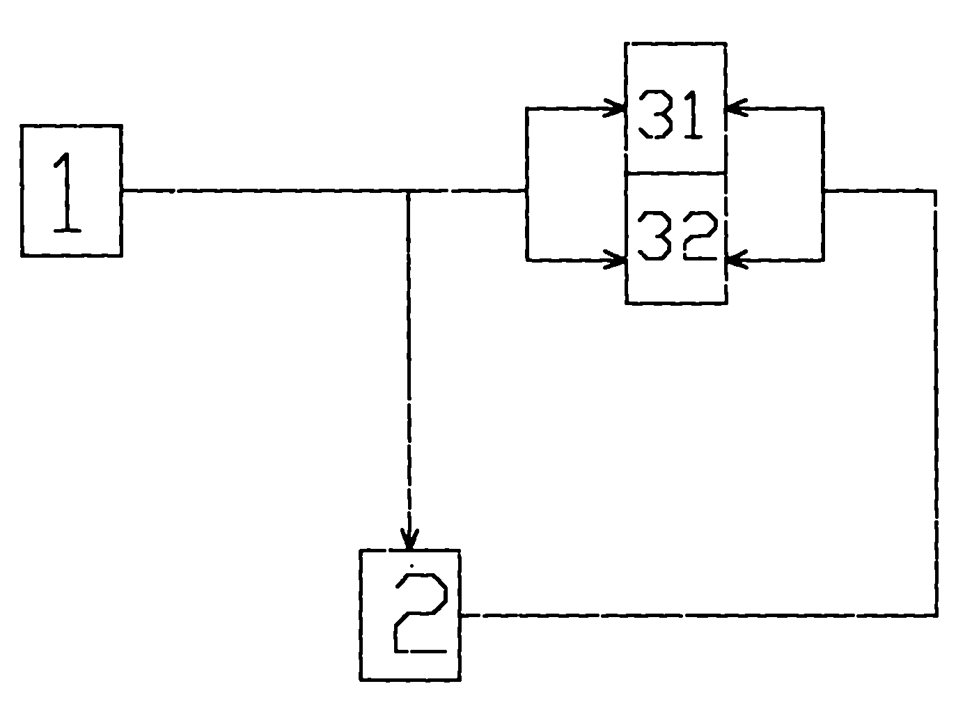
[0018] The LED street lamp energy-saving automatic control method of the present invention is as follows: figure 1 As shown, the chip of an LED light source (3) is made into two circuits (31) and (32) arranged in parallel to form LED light source one (31) and LED light source two (32), and then through the automatic control circuit (2 ), the power supply (1) is automatically added to the positive poles of LED light source one (31) and LED light source two (32) at the same time at regular intervals to make it work at the same time, or to be added to LED light source one (31) or LED light source two separately alternately On the positive pole of (32), make one of them alternately work alone.

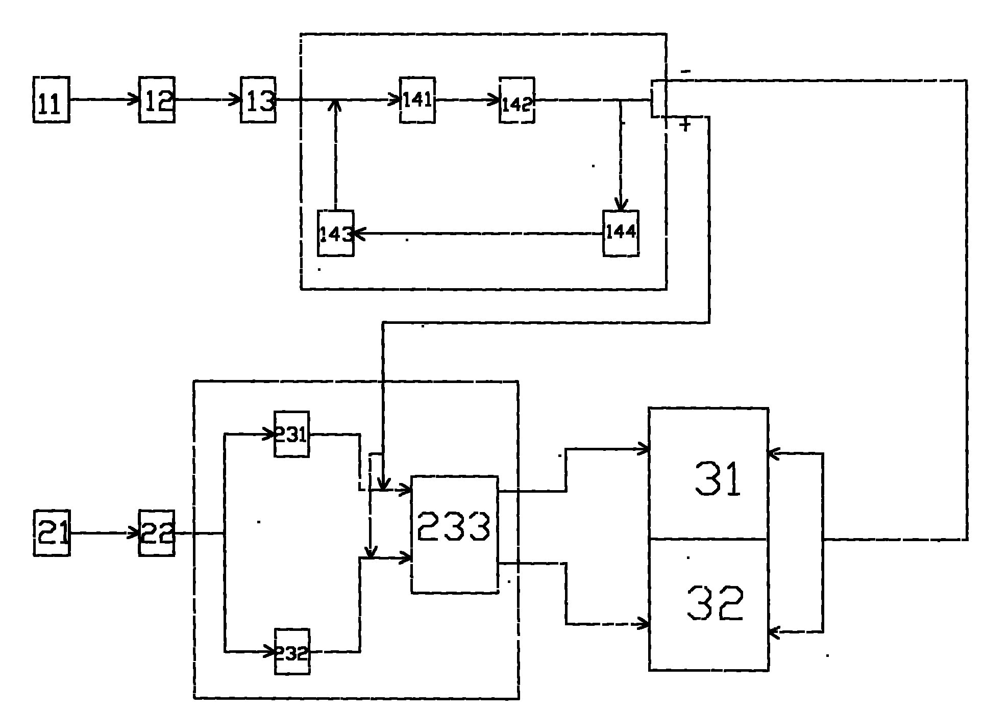
[0019] According to the above LED street lamp energy-saving automatic control method, a kind of LED street lamp energy-saving automatic...


PUM


Abstract

The invention relates to a light-emitting diode (LED) street lamp energy-saving automatic control method and device. The device comprises a power supply, an automatic control circuit and an LED light source, wherein the power supply is a flyback power supply containing an AC protection circuit, a common-mode rejection circuit, a rectifier filtering circuit and a constant pressure constant currentcircuit which are connected successively; the automatic control circuit comprises a clock circuit, a SCM circuit and a switch circuit which are connected successively; and the LED light source comprises an LED light source 1 and an LED light source 2 which are arranged in a chip in parallel, the cathode is directly connected with the negative electrode of the power supply, the anode is connected with the automatic control circuit; and the automatic control circuit periodically and automatically connects the positive electrode of the power supply with the anodes of the LED light source 1 and the LED light source 2 according to the illumination brightness demands of streets to ensure that the two LED light sources work at the same time, or periodically, automatically and separately connectsthe positive electrode of the power supply with the anode of the LED light source 1 or the LED light source 2 to ensure that the LED light source 1 or the LED light source 2 works. The invention solves the problems of saving the energy and prolonging the service life of the LED street lamp, and has the obvious advantages of simple structure, good illumination quality for streets and no illumination dark space.

Description

technical field [0001] The invention relates to an energy-saving automatic control method and device for LED street lamps, belonging to the field of energy-saving automatic control of LED street lamps. Background technique [0002] At present, there are basically two types of automatic energy-saving control methods and devices for LED street lamps: one is to control the current size of LED street lamps, that is, to control the output power. When the need is large, let the output power of the LED street lamp be higher, that is, the full power output. In the middle of the night, when the flow of people and traffic on the road is small, and it is only necessary to maintain the proper lighting brightness of the road, let the output power of the LED street lamp be lower, so as to achieve energy saving. Purpose; The other is to set two LED light sources in a street lamp lampshade, pack them in two bulbs, and supply power to them separately. In the evening, both LED light sources a...

Claims


Application Information

Patent Timeline
IPC IPC(8): H05B37/02
CPCY02B20/42Y02B20/72Y02B20/40
Inventor 王春
Owner 王春
Why Eureka
Try Eureka