Magnetic-acoustic electrical impedance imaging method and device

A technology of electrical impedance imaging and imaging, applied in medical science, sensors, diagnostic recording/measurement, etc.

Active Publication Date: 2010-08-04
INST OF ELECTRICAL ENG CHINESE ACAD OF SCI
View PDF3 Cites 32 Cited by
  • Summary
  • Abstract
  • Description
  • Claims
  • Application Information

AI Technical Summary

Problems solved by technology

The present invention can be used to measure the electrical impedance distribution of organisms

Method used


Image

  • Magnetic-acoustic electrical impedance imaging method and device
  • Magnetic-acoustic electrical impedance imaging method and device
  • Magnetic-acoustic electrical impedance imaging method and device

Examples


Embodiment Construction

[0032] The present invention will be further described below in conjunction with the accompanying drawings and specific embodiments.

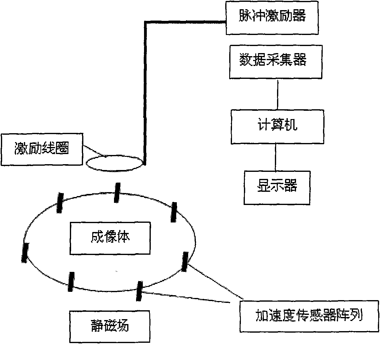
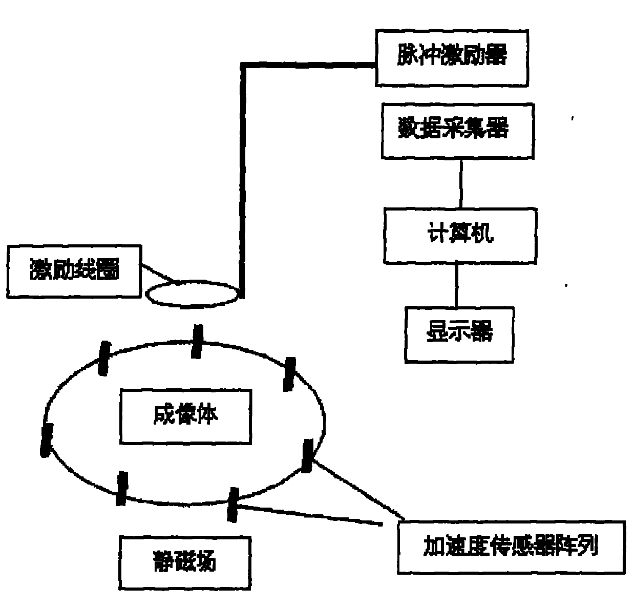
[0033] The magnetoacoustic electrical impedance imaging method of the present invention utilizes the pulse exciter that connects excitation coil to make excitation coil produce transient current J S , an induced current is generated in the imaging body, and the induced current is in the static magnetic field B 0 The Lorentz force F is generated under the action, and the Lorentz force F causes the particle vibration of the imaging body, excites the ultrasonic signal, and the ultrasonic signal propagates to the imaging body. The invention uses an acceleration sensor to measure the displacement waveform u at the location of the acceleration. According to the nonlinear relationship between the displacement waveform u and the conductivity, the conductivity image of the imaging body is reconstructed.

[0034] As shown in the drawings, the magnetoac...


PUM


Abstract

The invention provides a magnetic-acoustic electrical impedance imaging method. The method is characterized by measuring a Lorentz force vibration displacement waveform signal generated under the action of a static magnetic field due to an inductive loop excited by a pulse magnetic field by using an acceleration sensor and acquiring an electric conductivity image of an imaging body through image reconstruction according to nonlinear relation between the displacement waveform signal and the electric conductivity. The device which adopts the method comprises a pulse exciter, exciting coils, a magnetostatic body, an acceleration sensor array, a data acquisition unit and a computer, wherein the exciting coils and the magnetostatic body are arranged on two sides of the imaging body; the acceleration sensor array are distributed surrounding the imaging body; the pulse exciter is connected with the exciting coils through cables; and the acceleration sensor array, the data acquisition unit and the computer are connected in turn.

Description

technical field [0001] The invention relates to a medical imaging method and device, in particular to a magnetoacoustic electrical impedance imaging method and device. Background technique [0002] The sensitivity and spatial resolution of traditional electrical impedance imaging are not high. To solve this problem, the University of Minnesota (YuanXu and Bin He 2005 Magnetoacoustic tomography with magnetic induction (MAT-MI) Phys.Med.Bio1.50 5175-5187) proposed Inductive magnetoacoustic electrical impedance imaging method. The main principle of this method is: the imaging target is placed in the static magnetic field B 0 , with a pulsed magnetic field B 1 After the current excites the imaging target, an induced current J is generated in it, and the current generates a Lorentz force F=J×B under the action of the static magnetic field 0 , thus exciting the sound pressure signal p. This imaging method is based on the theoretical basis for the sound pressure wave equation ...

Claims


Application Information

Patent Timeline
Patent Type & Authority Applications(China)
IPC IPC(8): A61B5/055A61B5/053
Inventor 刘国强夏慧贺文静张洋李艳红徐路遥
Owner INST OF ELECTRICAL ENG CHINESE ACAD OF SCI
Why Eureka
Try Eureka