Cooling tank device of hot-rolling perforation machine set

A hot-rolled piercing and cooling groove technology, applied in metal rolling, metal rolling, manufacturing tools, etc., can solve the problems of inaccurate cam switch control, unintuitive adjustment of cam switches, easy twisting and deflection of the claws, etc. Simple, small footprint, accurate stop position effect

Inactive Publication Date: 2010-08-04
TAIYUAN HEAVY IND
View PDF7 Cites 10 Cited by
  • Summary
  • Abstract
  • Description
  • Claims
  • Application Information

AI Technical Summary

Problems solved by technology

[0005] The current cooling tank device has the following disadvantages: the mechanism is complicated, the floor area is large, the water source is wasted, and the cooling effect is not good. figure 2 It can be seen that the ejector pin that needs to be cooled is the uppermost part of the water in the cooling tank, so the cooling effect is poor; when changing the specifications of the ejector pin, it is necessary to adjust the adjustment device, which is more troublesome; the ejector pin is easy to run when it rolls on the slide rail It is biased, so that the claws cannot catch the ejector rod; the four support wheel roller seats and the two bearings will be oxidized and rusted after being soaked in water for a long time, which will affect the rotation of the mechanism; the rotating shaft is connected into a whole through two couplings , so the claws of the 10 runners installed on the rotating shaft are easy to twist and deflect. The stop position A of each rotation of the runner is not easy to correspond to. In addition, because the cam switch has passed through the transmission of the sprocket chain, the transmission gap of the sprocket chain and the slack of the chain will also cause inaccurate control of the cam switch.

Method used


Image

  • Cooling tank device of hot-rolling perforation machine set
  • Cooling tank device of hot-rolling perforation machine set
  • Cooling tank device of hot-rolling perforation machine set

Examples


Embodiment Construction

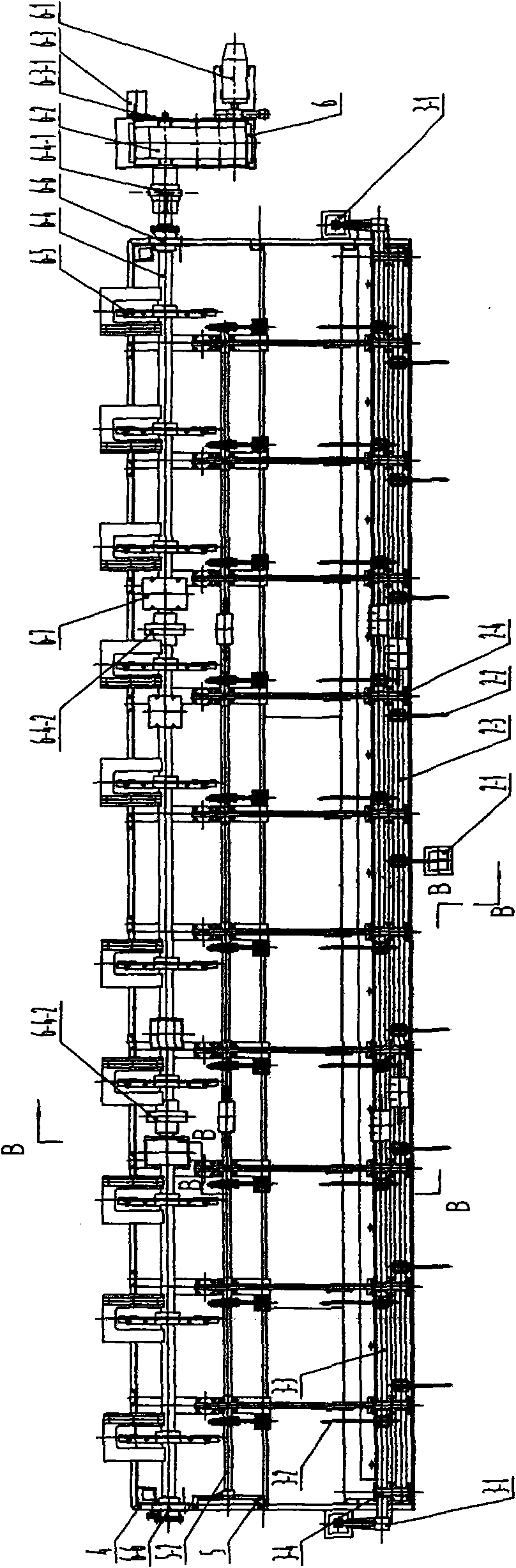
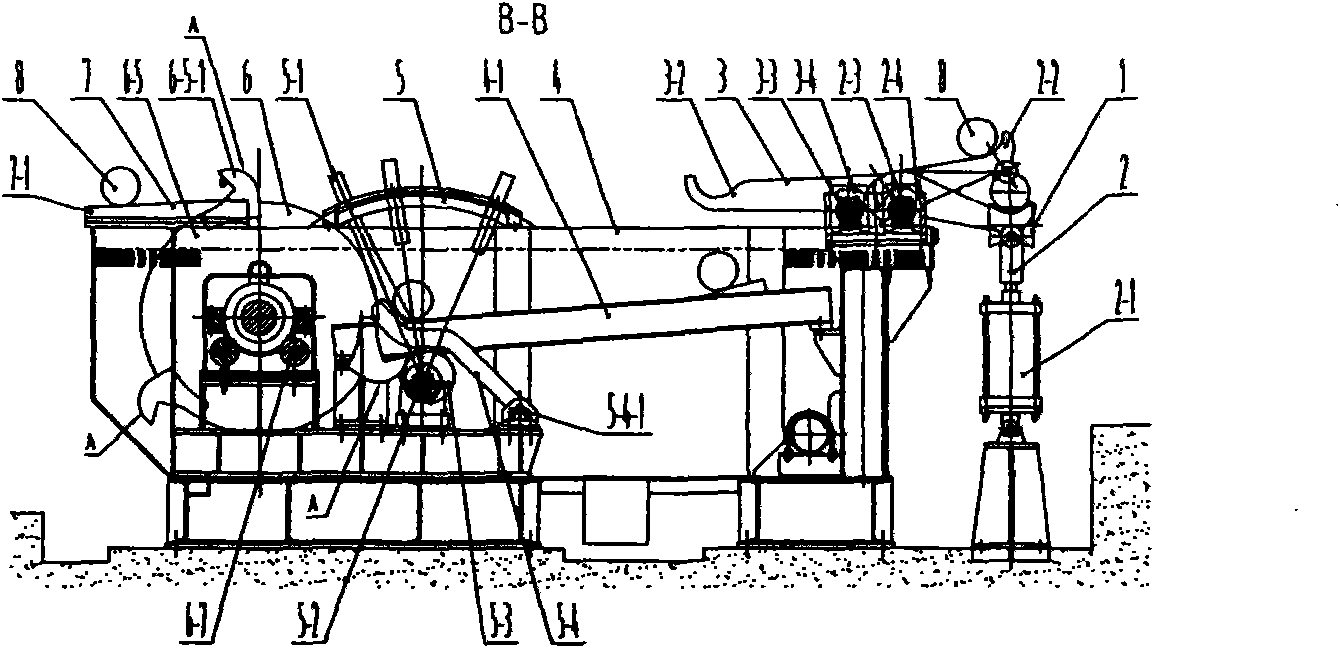
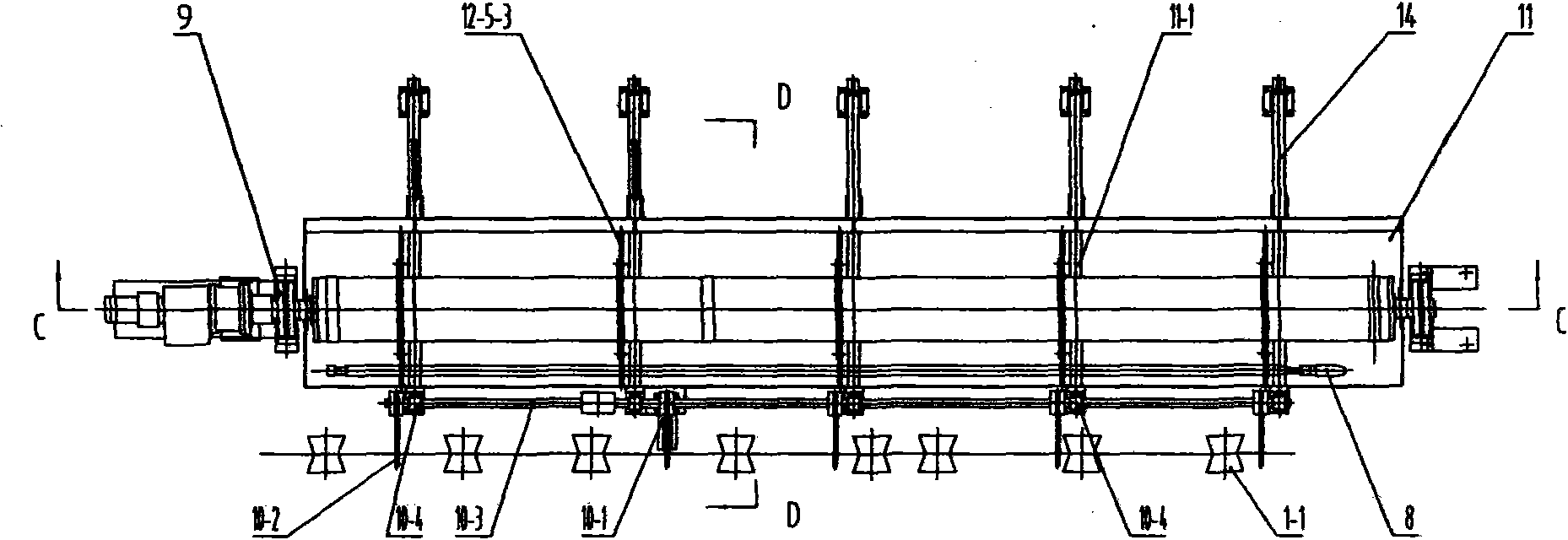
[0022] Such as image 3 , 4 , 5, 6, and 7, a cooling tank device for a hot-rolled piercing unit, including: a feed roller table 1, a dial-in device 10, a cooling tank 4, a barrel device 9, a controller 11, and a discharge table 7 . The feeding roller table 1 is composed of a plurality of rollers 1-1; the dial-in device 10 is composed of a hydraulic cylinder 10-1, five dialing structures 10-2, a rotating shaft 10-3, five The bearing seat 10-4 is formed, the middle trunnion of the hydraulic cylinder 10-1 is hinged on the cooling tank 4, and the piston rod earring of the hydraulic cylinder 10-1 is hinged at the middle Z of one of the five material dialing structures 10-2. The end of each dialing mechanism 10-2 is connected on a rotating shaft 10-3, and the rotating shaft 10-3 is connected in five bearing seats 10-4 and can rotate, and the five bearing seats 10-4 are fixed in the cooling tank 4; the cooling tank 4 is a large welded metal tank body, five semicircular ejector sli...


PUM


Abstract

The invention discloses a cooling tank device of a hot-rolling perforation machine set, relating to hot-rolling perforation machine set equipment. The invention solves the problems that the existing cooling tank device has large occupied area, large cooling water requirement amount, poor cooling effect and inaccurate mandril control so as to affect normal production operation. The invention is characterized in that in-bound equipment is an in-bound device 10 which is composed of a hydraulic cylinder 10-1, five material toggling grooves 10-2, a rotary shaft 10-3 and five bearing pedestals 10-4; the bottom of a cooling trough 4 is welded with five semicircular mandril slideways 4-2; a rotary device utilizes a support frame arranged outside the cooling trough and a rotary drum device 9 arranged right above the cooling trough 4; and a control mechanism is a controller 11 consisting of a profile modelling disk 11-1 and an approach switch 11-2.

Description

technical field [0001] The invention belongs to steel rolling machinery equipment, in particular to a cooling tank device used by a hot rolling piercing unit in the production of seamless steel pipes. Background technique [0002] In the current production of seamless steel pipes, the hot-rolled piercing unit with circulating ejector pins is used. During the piercing process, multiple ejector pins need to be cooled in turn to ensure the allowable use temperature of the ejector pins; after working in red steel at 1000 ℃ The ejector rod or mandrel enters a cooling tank filled with water in sequence, and then a special mechanical device that is taken out and reused is called a cooling tank device. [0003] Taking the circulation ejector as an example, the current cooling tank device, such as figure 1 , 2 As shown: It is composed of feeding roller table 1, dial-in mechanism 2, putting device 3, cooling tank 4, adjusting device 5, wheel device 6, and discharging table 7. The f...

Claims


Application Information

Patent Timeline
Patent Type & Authority Applications(China)
IPC IPC(8): B21B25/04B21B19/04
Inventor 张良夫秦臻郭建明
Owner TAIYUAN HEAVY IND
Why Eureka
Try Eureka