
Semi-precast beam

A semi-prefabricated, beam-body technology, applied in the direction of joists, girders, truss beams, etc., can solve the problems of long construction period, large consumption of formwork and support materials, and difficult control of project quality, so as to achieve construction efficiency and construction quality Improved effect

Inactive Publication Date: 2010-08-04
管乃彦
View PDF5 Cites 13 Cited by
  • Summary
  • Abstract
  • Description
  • Claims
  • Application Information

AI Technical Summary

Problems solved by technology

[0002] With the acceleration of China's urbanization process, the society's demand for high-rise residences is becoming increasingly urgent. Traditional buildings are constructed on site (including steel bar binding, formwork support, concrete pouring, etc.). The technical level is uneven, and the amount of high-altitude operations is large. There are problems such as large consumption of formwork and support materials, low construction efficiency, long construction period, and difficult control of project quality.
However, the post-cast joint treatment in the existing prefabricated component construction methods at home and abroad can only meet the corresponding precast concrete specifications, but cannot meet the technical requirements of China's cast-in-place reinforced concrete. technology exploration

Method used


Image

  • Semi-precast beam
  • Semi-precast beam
  • Semi-precast beam

Examples


Embodiment 1

[0040] Embodiment 1 Trapezoidal section semi-prefabricated beam

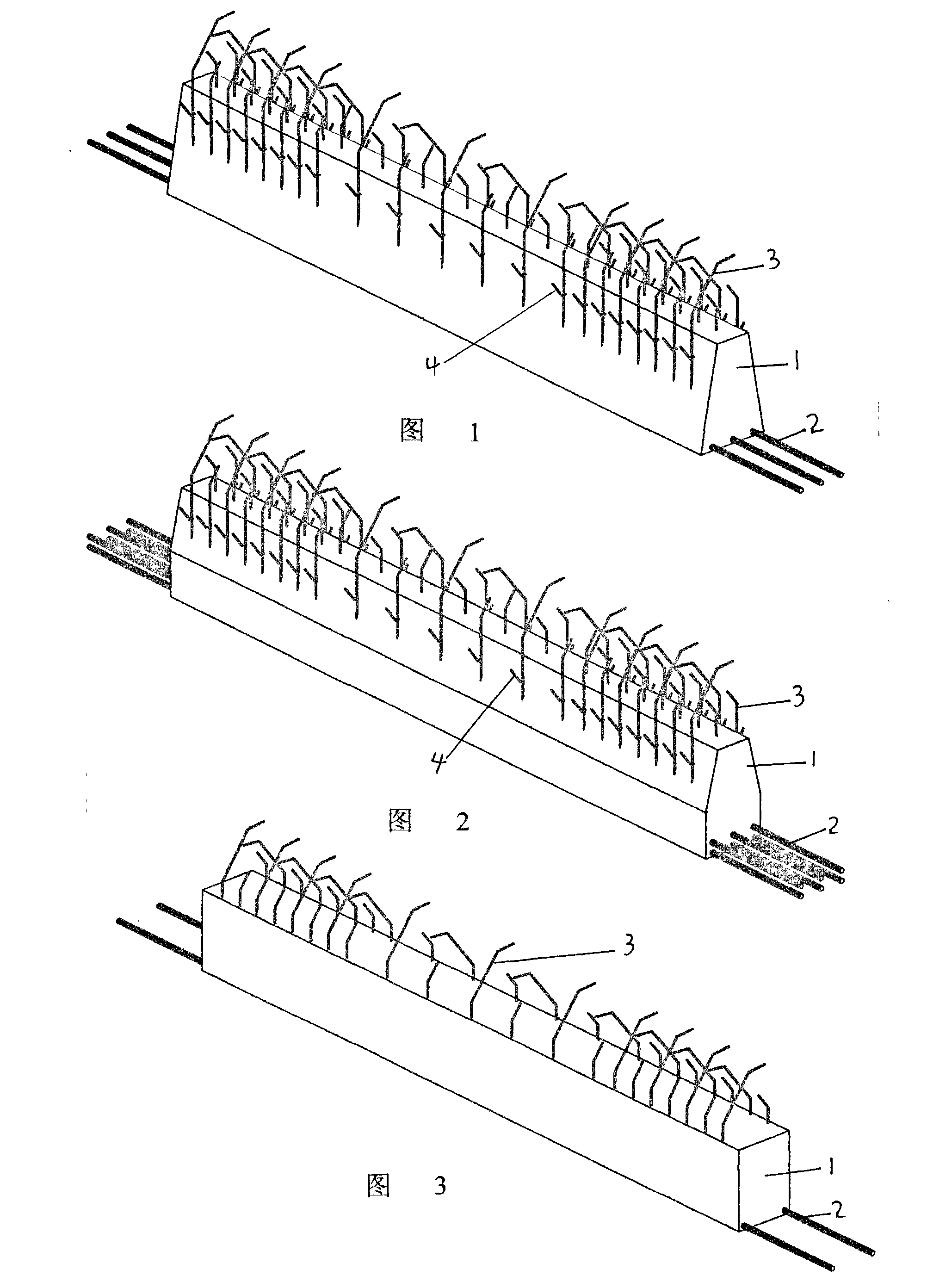
[0041] Trapezoidal cross-section semi-prefabricated beam, its structure is as follows figure 1 As shown, it includes trapezoidal cross-section beam body 1 and stressed steel bars 2. There are three stressed steel bars 2 in a row, which are distributed in the lower part of beam body 1 and protrude outside beam body 1. On beam body 1, open stirrups 3 extend Out of the top of the beam body, the transverse tension bars 4 stretch out from the side of the beam body.

Embodiment 2

[0042] Embodiment 2 Semi-prefabricated beam with table-shaped cross-section

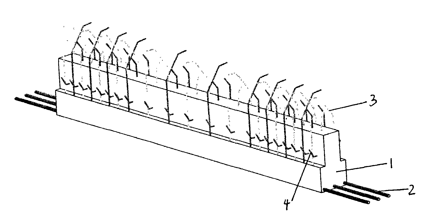
[0043] Semi-prefabricated girder with trapezoidal section, its structure is as follows figure 2 As shown, it includes a table-shaped cross-section beam body 1 and two rows of stressed steel bars 2 in the lower part. There are 3 stressed steel bars 2 in each row, which are distributed in the lower part of the beam body 1 and protrude outside the beam body 1. The open stirrup bars in the beam body 1 3. Stretch out the top of the beam body, stretch the ribs 4 horizontally, and stretch out the side of the beam body.

Embodiment 3

[0044] Embodiment 3 Rectangular section semi-prefabricated beam

[0045] Rectangular cross-section semi-prefabricated beam, its structure is as follows image 3 As shown, it includes a rectangular cross-section beam body 1 and a stressed steel bar 2. There are two stressed steel bars 2 in a row, distributed at the lower part of the beam body 1 and protruding out of the beam body 1, and the open stirrup 3 protrudes from the beam body 1. the top of the beam.


PUM


Abstract

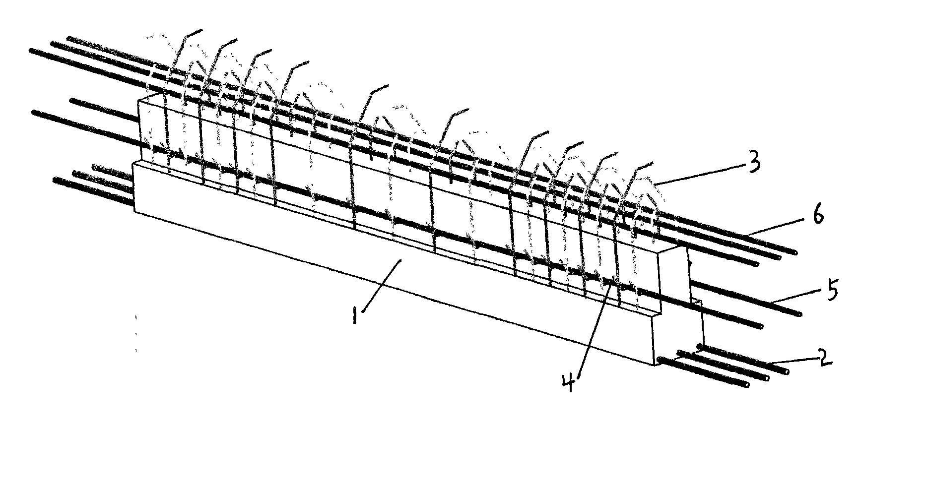
The invention provides a semi-precast beam, which mainly comprises a beam body and steel bars (a general name of stressed steel bars, stirrups and tie bars), and is characterized in that: only the stressed steel bars and the stirrups on the lower part are pre-arranged in the semi-precast beam; and the beam body is exposed on a banding or welding part of the stirrups and other post-arranged stressed steel bars to prevent the steel bars on the upper part from impeding construction. The semi-precast beam has the advantages that: the steel bars of the semi-precast beam do not conflict with the steel bars of other components in the process of installation, so that the treatment of the steel bars at joints meets the requirement of a specification of a reinforced concrete structure; a beam holding component bears the construction load instead of a full scaffold by using a principle of simply supported beams; the connection of the steel bars and the banding of templates are performed on the floor, so that the safety of workers is ensured, and the construction efficiency and the construction quality are obviously improved; the amount of high-altitude operation is substantially reduced; and the post-casting of concrete is operated on the floor, and the amount of the post-cast concrete is substantially reduced, so the construction speed is substantially improved.

Description

technical field [0001] This invention relates to building element beams. Background technique [0002] With the acceleration of China's urbanization process, the society's demand for high-rise residences is becoming increasingly urgent. Traditional buildings are constructed on site (including steel bar binding, formwork support, concrete pouring, etc.). The technical level is uneven, and the amount of high-altitude operations is large, and there are problems such as large consumption of formwork and support materials, low construction efficiency, long construction period, and difficult control of project quality. However, the post-cast joint treatment in the existing prefabricated component construction methods at home and abroad can only meet the corresponding precast concrete specifications, but cannot meet the technical requirements of China's cast-in-place reinforced concrete. technology exploration. Contents of the invention [0003] The purpose of the invention is ...

Claims


Application Information

Patent Timeline
Patent Type & Authority Applications(China)
IPC IPC(8): E04C3/20
Inventor 管乃彦
Owner 管乃彦
Learn More