Supercharge Your Innovation With Domain-Expert AI Agents!

Pressure actuated fuel injector

A technology of fuel injectors and injection valves, which is applied in the direction of fuel injection devices, injection devices, injection devices, etc.

Active Publication Date: 2010-08-04
GM GLOBAL TECH OPERATIONS LLC
View PDF0 Cites 0 Cited by
  • Summary
  • Abstract
  • Description
  • Claims
  • Application Information

AI Technical Summary

Problems solved by technology

Friction between the actuating member and the valve mechanism may create difficulties in maintaining the valve mechanism in a fully seated condition when the injection event is complete

Method used


Image

  • Pressure actuated fuel injector
  • Pressure actuated fuel injector
  • Pressure actuated fuel injector

Examples


Embodiment Construction

[0012] The following description is merely exemplary in nature and is in no way intended to limit the invention, its application or uses. It should be understood that throughout the drawings, corresponding reference numerals indicate like or corresponding parts or features.

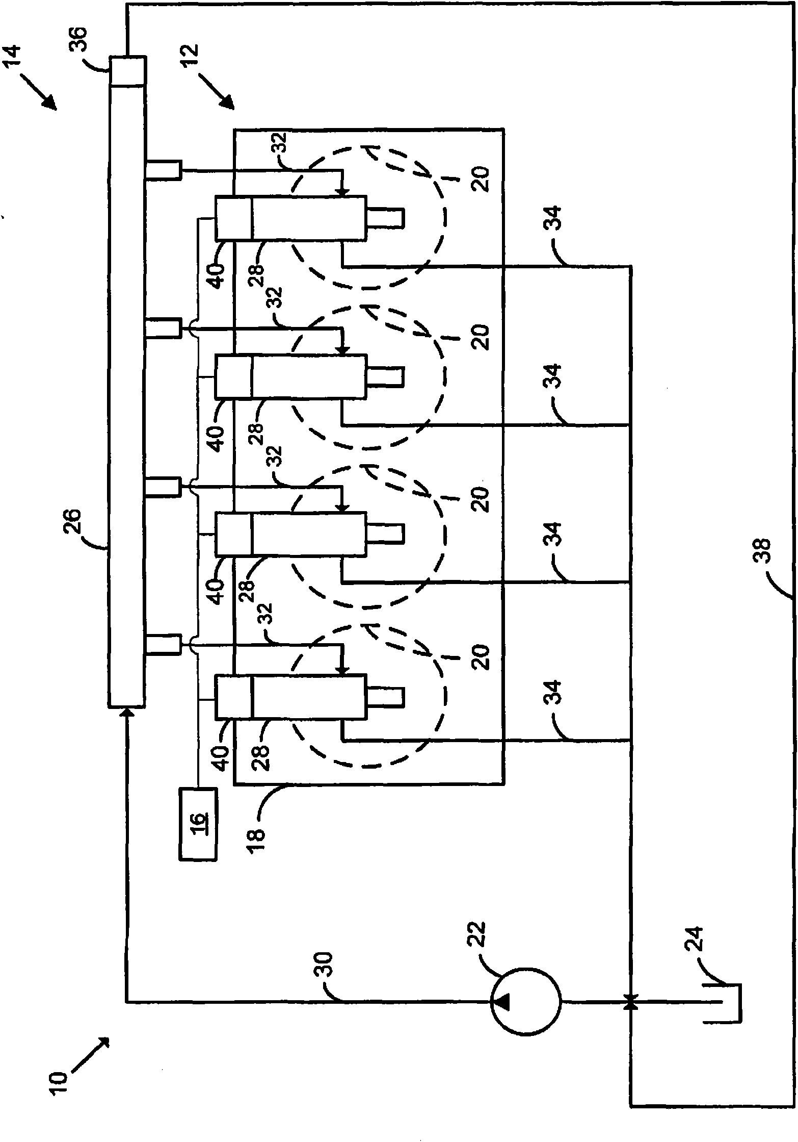
[0013] refer to figure 1 , an exemplary engine assembly 10 is schematically shown. Engine assembly 10 may include engine 12 and a control module 16 in communication with fuel system 14 . In the illustrated example, the engine 12 may include an engine block 18 that defines a plurality of cylinders 20 in communication with the fuel system 14 . Although engine 12 is shown as a four-cylinder engine in this disclosure, it should be understood that the present teachings apply to various engine configurations and are in no way limited to the configuration shown.

[0014] The fuel system 14 may include a fuel pump 22 , a fuel tank 24 , a fuel rail 26 , fuel injectors 28 , a main fuel supply line 30 , a seconda...


PUM


Abstract

The present invention relates to a pressure actuated fuel injector. An engine assembly may include a fuel injector having a housing, an actuation mechanism, and a valve member. The housing may define a high pressure region, a low pressure region, a longitudinal bore, and a valve seat having an aperture extending therethrough. The actuation member may be disposed within the longitudinal bore and may include a first axial end surface. The valve mechanism may include a second axial end surface abutting the first axial end surface. The first and second axial end surfaces define an outer contact perimeter and a chamber within the outer contact perimeter. A radial surface area defined by the chamber formed by the first and second axial end surfaces may be at least 25 percent of a radial surface area defined within the outer contact perimeter.

Description

technical field [0001] The present invention relates to engine fuel systems, and more particularly to fuel injectors. Background technique [0002] The statements in this section merely provide background information related to the present disclosure and may not constitute prior art. [0003] The pressure-actuated fuel injector may include a pressurized fuel supply for opening and closing the nozzle opening. The injector may include an actuation member and a valve mechanism to selectively open and close the leak path between the low pressure and high pressure regions of the injector. Opening the leak passage reduces the closing bias force applied to the injection valve to open the nozzle opening. When the leakage passage is closed, the injection valve may be displaced to close the nozzle opening. Frictional forces between the actuating member and the valve mechanism can create difficulties in maintaining the valve mechanism in a fully seated condition when the injection e...

Claims


Application Information

Patent Timeline
IPC IPC(8): F02M61/04F02M61/18F02M61/14
CPCF02M47/027B05B1/302B05B1/3013F02M63/0036F02M63/007
Inventor R·D·斯特劳布
Owner GM GLOBAL TECH OPERATIONS LLC
Features
  • R&D
  • Intellectual Property
  • Life Sciences
  • Materials
  • Tech Scout
  • Unparalleled Data Quality
  • Higher Quality Content
  • 60% Fewer Hallucinations
Learn More