Keyboard, key direction switch device and respective assembling processes

A lift switch, keycap technology, applied in electrical switches, electrical components, circuits, etc., can solve the problems of narrowing the keys, the overall size of the keys is too large, the size of the keys is large, etc., to achieve smooth motion effect, narrow space area, The effect of overall size reduction

Active Publication Date: 2012-08-22
G TECH TECH
View PDF1 Cites 0 Cited by
  • Summary
  • Abstract
  • Description
  • Claims
  • Application Information

AI Technical Summary

Problems solved by technology

The existence of overlapping areas brings cumbersome assembly process, which obviously does not meet the requirements of high-efficiency production;
[0007] In addition, the technical solution disclosed in the CN101599379 patent announcement needs to accommodate the synchronous part 21 between the two frames 23 and 25, and the through hole 210 for the elastic part 31 to pass through must be preset between the synchronous parts 21. Therefore, the width of the space enclosed by the frames 23 and 25 must be much larger than the radial dimension of the elastic member 31, so as to accommodate both the elastic member 31 and the synchronous member 21 at the same time, which will cause the overall size of the keys to be too large, thus affecting the keyboard overall size of
Even if all the members of the button are reduced in the same proportion, the ratio between the radial dimension of the elastic member 31 and the side length of the rectangular area formed by the two frames 23 and 25 still cannot be improved, so each component of the button In the case of a given proportional relationship, the size of the buttons formed by the known technical solution is relatively large, which cannot be applied to some occasions that require narrow button layout.

Method used


Image

  • Keyboard, key direction switch device and respective assembling processes
  • Keyboard, key direction switch device and respective assembling processes
  • Keyboard, key direction switch device and respective assembling processes

Examples


Embodiment Construction

[0050] Below in conjunction with accompanying drawing and embodiment the present invention will be further described:

[0051] Keyboard (not shown) of the present invention, as the input device of electronic instrument, is applicable to personal computer, mobile phone, notebook computer and netbook etc., has a plurality of ultra-thin keys, and each key is made of a key lifting switch device, so The keyboard of the present invention is formed after a plurality of key lift switch devices are assembled according to the preset arrangement of the keyboard layout. Similarly, the assembly process of the key lift switch devices is also applicable to the formed keyboard.

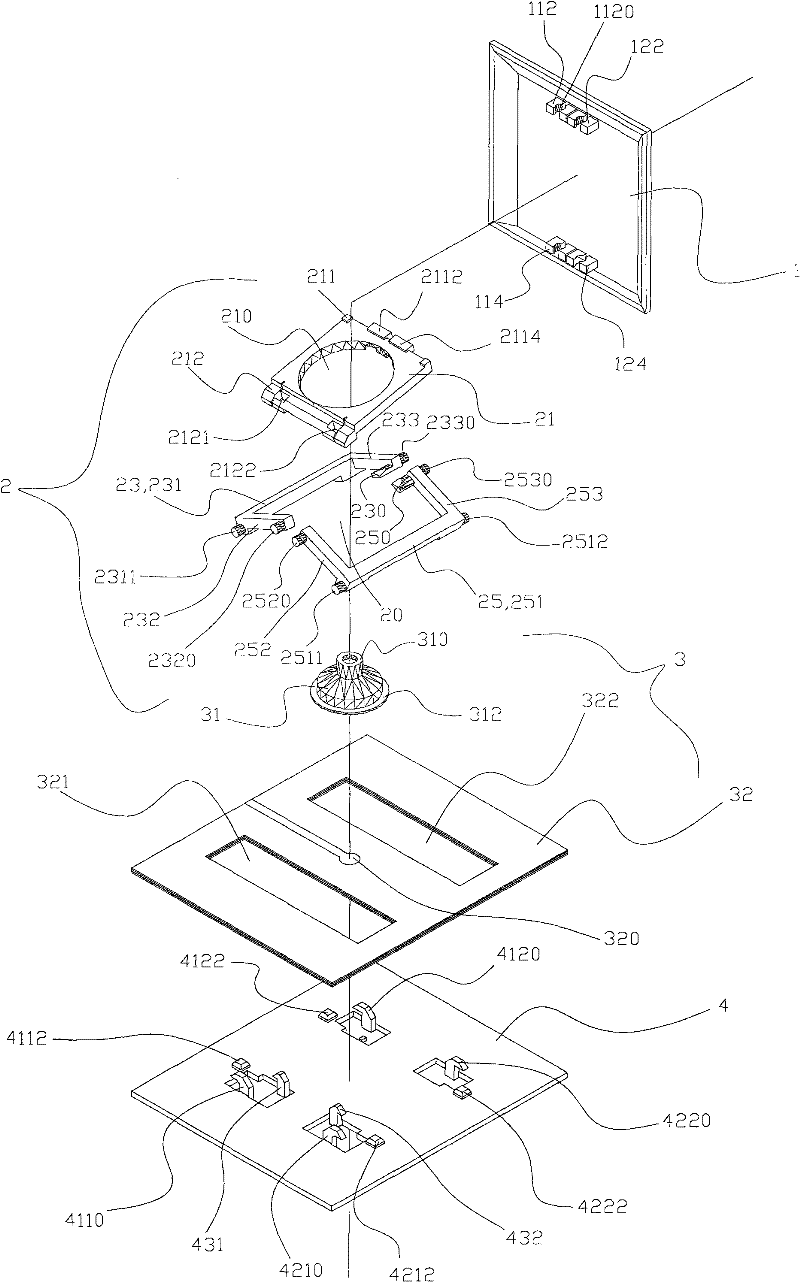
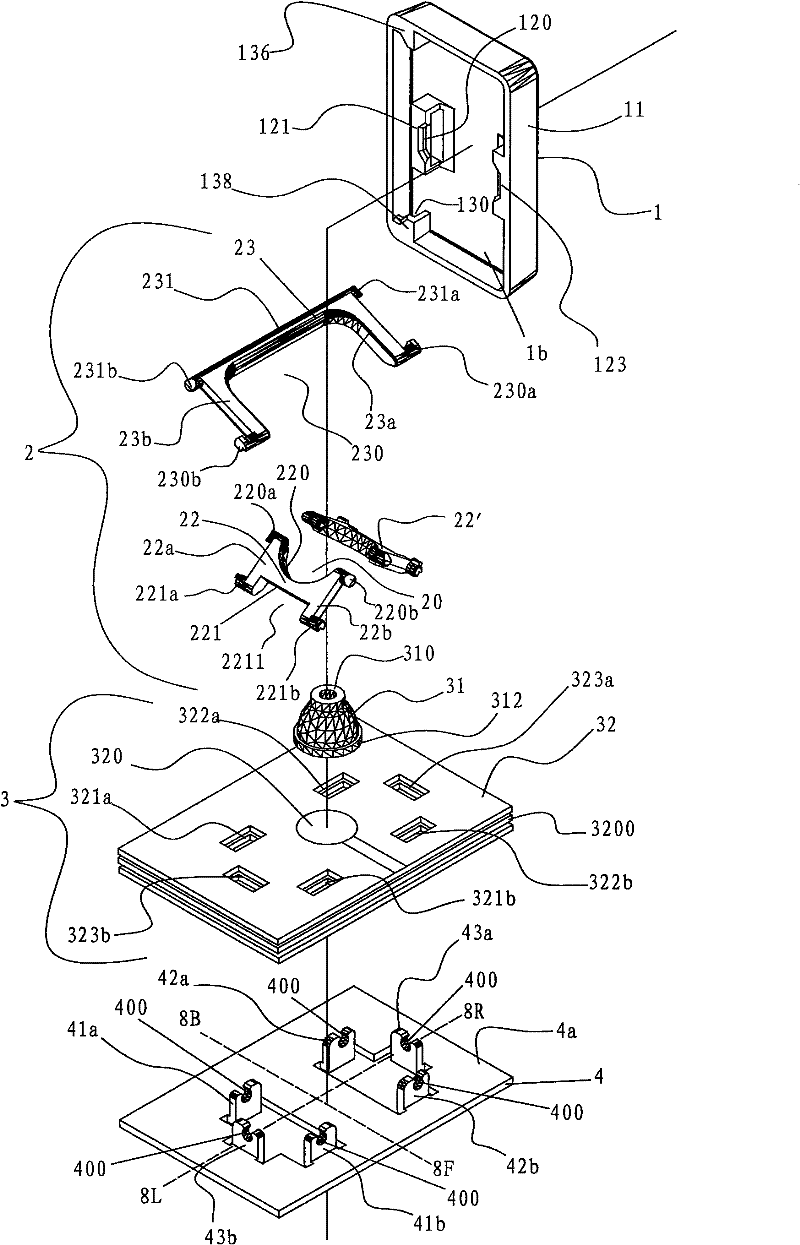
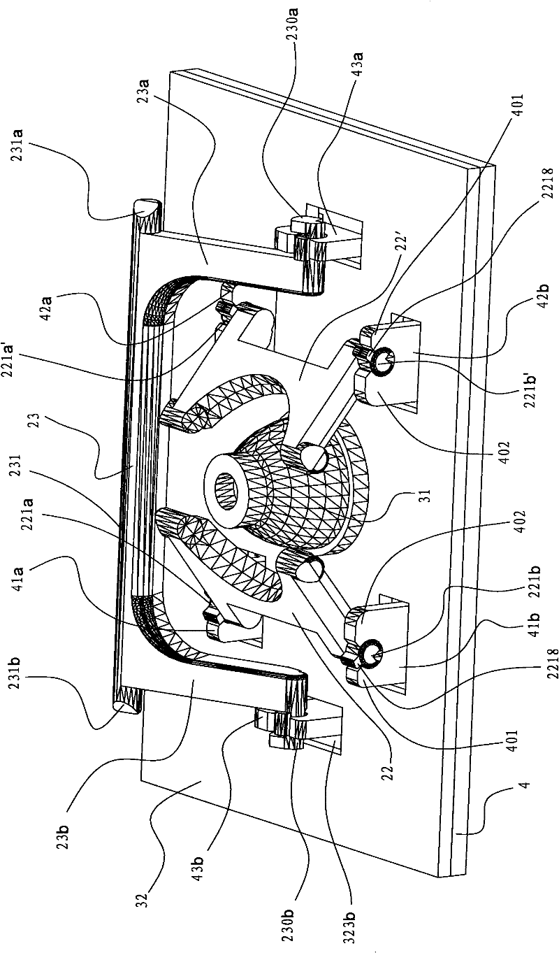
[0052] see figure 2 The keyboard of the present invention includes a support plate 4, a switch mechanism 3, a telescopic assembly 2 and a keycap 1, and the support plate 4 is provided for the switch mechanism 3, the telescopic assembly 2 and the keycap 1 for installation, and the switch mechanism 3 is installed on t...


PUM


Abstract

The invention discloses a keyboard, a key direction switch device and respective assembling processes. The main improvement is reflected in a telescopic component of the direction switch device. The telescopic component comprises a pair of frameworks and at least one synchronizing member, wherein the frameworks are oppositely arranged in a non-contact way and form a cavity; the far sides corresponding to the two frameworks are respectively pivoted on one of a support plate and a keycap; the near sides corresponding to the two frameworks are glidingly pivoted on both of the support plate and the keycap; the at least one synchronizing member causes synchronous lifting of the framework, wherein the first side is pivoted on one of the support plate and the keycap at the periphery of the framework, and the second side is glidingly pivoted on both of the support plate and the keycap; and the pivoting axle of the synchronizing member is perpendicular to respective pivoting axles of the two frameworks. The invention optimizes the structure inside the key, can reduce the size of the keyboard and the key, is beneficial to improving the assembling process and further improves the production efficiency as well as the yield of the keyboard.

Description

【Technical field】 [0001] The present invention relates to a keyboard, a key lift switch device and their respective assembly processes, in particular to a key lift switch device using ultra-thin keys, an applied keyboard and their respective assembly processes. 【Background technique】 [0002] In the CN101599379 patent announcement published on December 9, 2009, the applicant proposed a key lifting switch device and its assembly fixture and assembly process, abandoning decades of monopoly technology market relying on meshing or scissors "connecting" The key lifting switch device structure of the "rod part" is used instead of a pair of frames that are not in contact with each other and are formed with a cavity, combined with a synchronous piece that is used to suppress the synchronous lifting of the pair of frames to guide the lifting action of the keycap. , this technical improvement makes the key lifting switch device and its corresponding assembly process have a more simpli...

Claims


Application Information

Patent Timeline
Patent Type & Authority Patents(China)
IPC IPC(8): H01H13/26H01H13/705H01H13/7065H01H13/88
Inventor 黎柏松
Owner G TECH TECH
Why Eureka
Try Eureka