

Module connector
A connector and plug technology, applied in the direction of connection, connecting device parts, electrical components, etc., can solve the problems of large dislocation, the module cannot be smoothly installed and connected, and achieve the effect of avoiding wear, simple structure and easy operation.
- Summary
- Abstract
- Description
- Claims
- Application Information
AI Technical Summary
Problems solved by technology
Method used
Image

Examples
Embodiment Construction
[0023] Referring to the accompanying drawings, the structure of the present invention and its working process will be described in detail below.
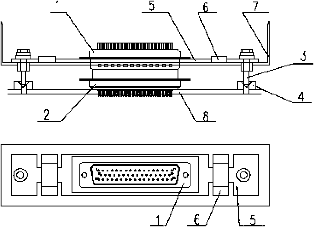
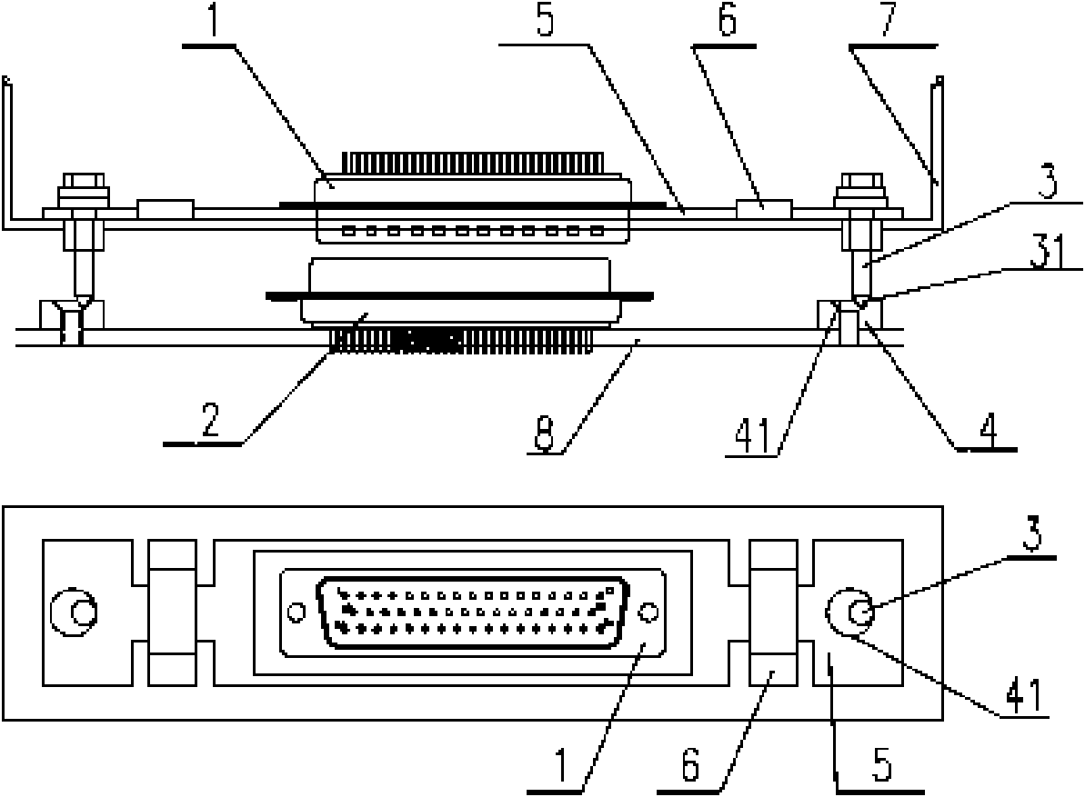
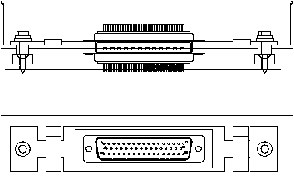
[0024] In order to solve the situation that there is a large deviation in the docking position of the plug and socket during the installation of the general module connector, which makes it difficult to quickly connect, this technology fixes the plug on the sliding plate that slides in contact with the module shell, and the plug is horizontally aligned with the module. The shell is separated, and the tolerance fit of the guide pin and the pin sleeve is used to make the plug linkage, so as to smoothly connect the plug on the module and the socket on the motherboard.
[0025] Such as figure 1 , the present invention mainly comprises parts such as plug 1, socket 2, guide pin 3, pin sleeve 4, sliding plate 5, pressing block 6. The present invention improves the installation method of the plug 1 inside the module in the common module co...
PUM
 Abstract
Description
Claims
Application Information