Bearing assembly for a journal, especially of a cross member of a universal joint

Inactive Publication Date: 2006-01-31
SPICER GELENKWELLENBAU
View PDF22 Cites 2 Cited by
  • Summary
  • Abstract
  • Description
  • Claims
  • Application Information

AI Technical Summary

Benefits of technology

[0005]It is an object of the present invention to provide a bearing assembly which ensures that, in spite of the existence of tolerances, the rolling-contact members are guided sufficiently and securely.
[0009]The assembly in accordance with the invention achieves a kind of rim guidance for the rolling-contact members which continue to be aligned parallel to the journal axis. This prevents the rolling-contact members from jamming. During the to- and fro-movement, it is possible to achieve a rolling-contact movement of the rolling-contact members between the outer face of the bearing journal and the running face of the bearing bore. Due to the resilient arrangement, this kind of guidance can be maintained across a large tolerance range. In addition, a better load distribution and a longer service life is achieved. The supporting portion is designed so that, at least along the journal axis, it provides spring travel.
[0010]In order to achieve a sufficiently high supporting force, the supporting portion is formed integral with the disk portion. The supporting portion includes a reinforcing insert made of metal or plastics. Alternatively, the supporting portion may be in the form of a Belleville-spring-like metal ring connected to the disk portion. For example, the Belleville-spring may be partially embedded in the disk portion which can be produced from plastics. The material for the disk portion and for the parts of the supporting portions connected thereto is preferably a polyamide material (PA). The PA material may be reinforced by fibers for instance and into which it is possible to embed friction-reducing lubricant constituents, such as molybdenum disulphide. As a result, it is possible to reduce the friction between the bottom face of the bearing element and the end face of the bearing journal and also between the rolling-contact members and the supporting face of the supporting portion. The stop ring may also include a coating of the above-mentioned material.

Problems solved by technology

Since the dimensions determining the distance between the running face of the stop ring and the supporting face of the pressure disk include tolerances, it is not guaranteed that the rolling-contact members are guided in a play-free manner in the axial direction, parallel to the journal axis.

Method used


Image

  • Bearing assembly for a journal, especially of a cross member of a universal joint
  • Bearing assembly for a journal, especially of a cross member of a universal joint
  • Bearing assembly for a journal, especially of a cross member of a universal joint

Examples


Embodiment Construction

[0024]The following description of the preferred embodiment(s) is merely exemplary in nature and is in no way intended to limit the invention, its application, or uses.

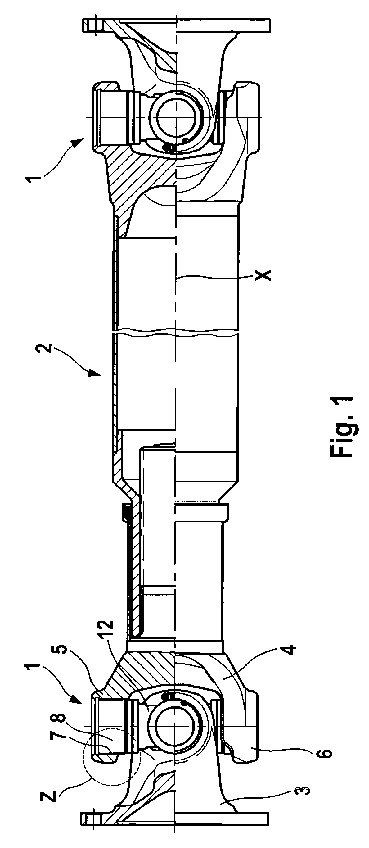
[0025]FIG. 1 shows a drive shaft with two universal joints 1 at the ends of a plunging unit 2. The individual parts are centered and arranged on the longitudinal axis X. The two universal joints may be identical, so that only one universal joint 1 needs to be described in detail. The universal joint 1 has a first joint yoke 3 and a second joint yoke 4. The first joint yoke 3 is connected to a flange. The second joint yoke is connected to one end of the plunging unit 2. If changes in angle occur between the two universal joints 1 at the ends of the plunging unit 2, the latter enables a change in length between the articulation centers of the universal joints 1.

[0026]The second joint joke 4 has a first yoke arm 5 and a second yoke arm 6. The arms 5 and 6 are arranged at a distance from one another and are symmetrically ...


PUM


Abstract

A bearing assembly for a bearing journal (13), especially of a cross member of a universal joint, has a bearing journal (13) with a cylindrical outer face (14), an end face (16) and a journal axis (15). A bearing element (8) has a cylindrical bearing bore (9) with a bottom face (11) and a running face (10) which is arranged at a radial distance from the outer face (14) of the bearing journal (13). Rolling-contact members (17), at their respective ends, include at least partially planar first end face (18) and second end face (19). The faces (18) and (19) are arranged between the running face (10) and the outer face (14). A stop face (20) includes an annular contact face (21) for the first end face (18) of the rolling-contact members (17). A pressure disk (22) is included with a disk portion (23) arranged between the end face (16) of the bearing journal (13) and the bottom face (11). A supporting portion (24) radially follows the disk portion (23) with reference to the journal axis (15). The supporting portion (24) is contacted by the second end faces (19) of the rolling-contact members (17). The supporting portion (24) is designed to be resilient.

Description

CROSS-REFERENCE TO RELATED APPLICATIONS[0001]This application claims priority to German Patent Application No. 10155761.2 filed Nov. 14, 2001, which application is herein expressly incorporated by reference.FIELD OF THE INVENTION[0002]The invention relates to a bearing assembly for a bearing journal of a cross member of a universal joint.BACKGROUND OF THE INVENTION[0003]A bearing assembly is described in U.S. Pat. No. 6,077,166 A. The bearing journal has a cylindrical outer face, an end face and a bearing axis. A bearing element is placed onto the bearing journal. The bearing element has a cylindrical bearing bore with a bottom face and a running face. The running face is arranged at a radial distance from the outer face of the bearing journal. Rolling contact members are positioned between the bearing journal and the bearing element. The rolling-contact members are cylindrical along at least part of their length. The rolling contact members, at their ends, have a planar first end f...

Claims


Application Information

Patent Timeline
Patent Type & Authority Patents(United States)
IPC IPC(8): F16D3/41F16D3/26F16C19/26F16C21/00F16C33/46F16C33/51F16C33/52F16C33/54F16C33/56F16C33/72F16D3/38
CPCF16C21/005F16C27/066F16C25/08F16C33/7809F16D3/385F16D2003/2023F16C17/04F16C19/466F16C2361/41F16D3/26
Inventor SCHULTZE, HANS-JURGEN
Owner SPICER GELENKWELLENBAU
Why Eureka
Try Eureka