

Binding machine
A binding machine and compression mechanism technology, applied in the field of binding machines, can solve problems such as dislocation of joints, hooking of cut pieces, and large thickness dimensions
- Summary
- Abstract
- Description
- Claims
- Application Information
AI Technical Summary
Problems solved by technology
Method used
Image

Examples
no. 1 approach
[0064] A first embodiment of the invention will be described below with reference to the drawings.
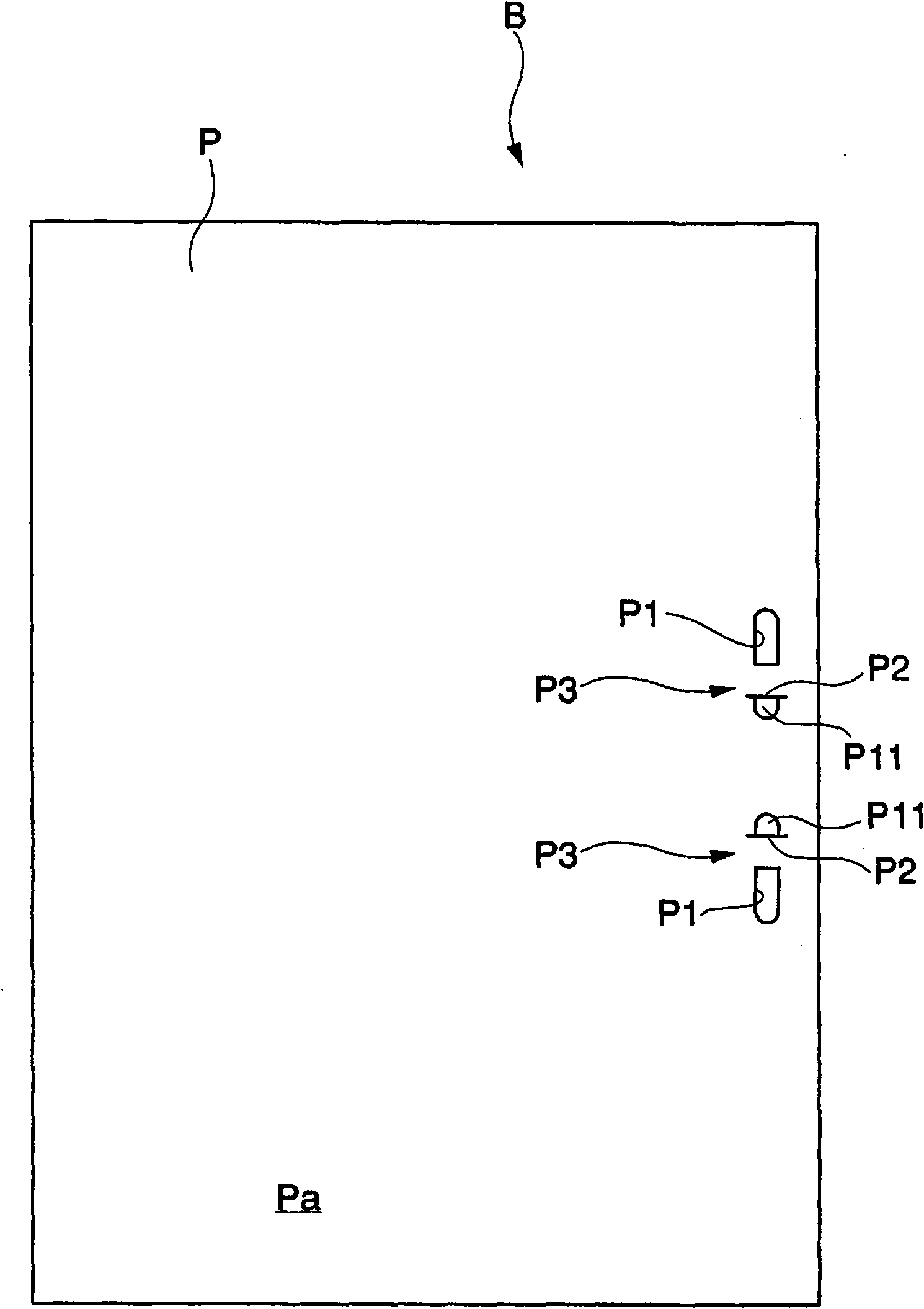
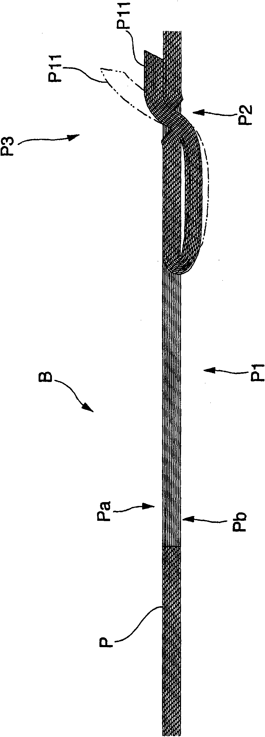
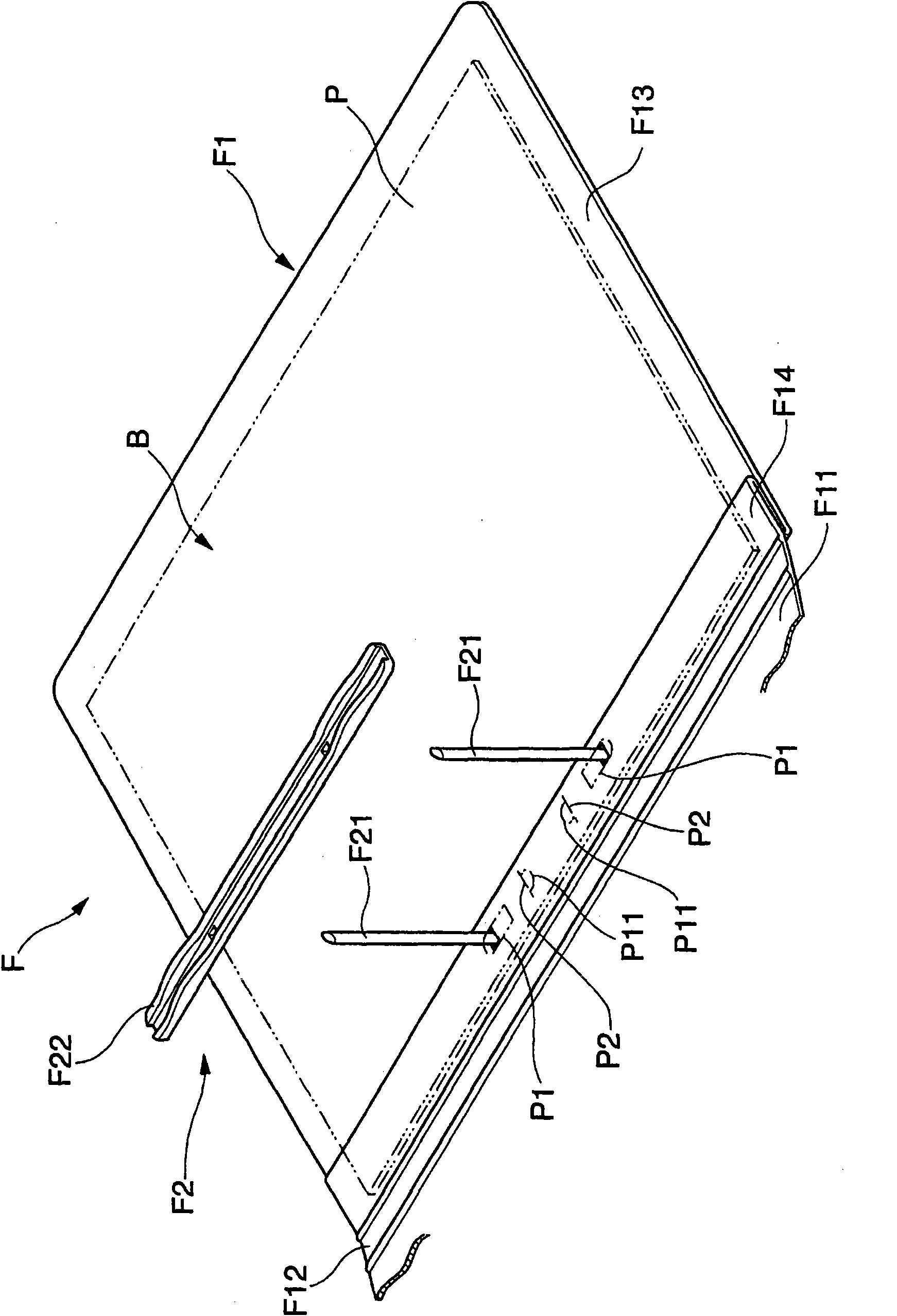
[0065] The binding machine 1 that this embodiment relates to, as Figure 1 to Figure 3 As shown, it can be suitably applied to the folder system of the booklet B in which one or more volumes are bound by the folder F. FIG.
[0066] Such as figure 1 with figure 2 As shown, the booklet B is formed by bundling a plurality of sheets made of homogeneous materials, for example, a plurality of sheets P, and these sheets P are joined to each other at two joining portions P3 set on the binding side. Each joint portion P3 is composed of: a binding hole P1 formed on each paper P by a punching blade 92 penetrating from the side Pa of the paper P; a pull-up cutting hole P2 adjacent to the binding hole P1 and Formed on each of the above-mentioned paper sheets P; the cut-out piece P11 is cut from the above-mentioned binding hole P1 toward the reverse side Pb of the paper sheet P. Then, b...
no. 2 approach
[0113] Next, refer to Figure 21 to Figure 37 The binding machine A1 that is directly used for implementing such a file system will be described.
[0114] This bookbinding machine A1 is a device for joining a plurality of sheets of paper P as sheets to produce the above-mentioned booklet B, such as Figure 21 As shown, it is equipped with: a stage A2 placed on the table; a main body A3 fixedly arranged on the stage A2; ユニツト), which can be lifted and accommodated in the main body A3 and equipped with a punching blade A92 and a cutting blade A91 described later; a paper holder A8 (paper base, paper tape reel seat), which ends the perforation at the blade changing unit A4 When moving up, it is used to lift the above-mentioned bound paper P; the operating handle A5 is installed on the above-mentioned main body A3 so as to be rotatable up and down in order to make the paper holder A8 and the blade changing unit A4 move.
[0115] Such as Figure 21 , Figure 25 with Figure 26...
PUM
 Abstract
Description
Claims
Application Information