
Full-automatic vacuum test tube uncapping machine

A test tube capping machine, fully automatic technology, applied in the direction of stopper removal, etc., can solve the problems of high cost, affecting test results, low efficiency, etc., and achieve the effect of simple and low manufacturing cost, simple capping process, and low manufacturing cost

Active Publication Date: 2010-08-11
珠海丰炎科技有限公司
View PDF6 Cites 20 Cited by
  • Summary
  • Abstract
  • Description
  • Claims
  • Application Information

AI Technical Summary

Problems solved by technology

In the process of vigorously opening the test tube cover, there will also be internal oscillations in the test tube, which may disperse the centrifuged samples and affect some test results. There are certain technical requirements for the operator.
Vigorously opening the test tube cap may also break the test tube and injure the operator's fingers
At the same time, in the process of opening the cover, there will be a certain amount of aerosol contamination of the patient's blood, which will endanger the health of the operator.
[0003] Although there have been some machines for opening vacuum test tube lids, these machines are often bulky, complex in structure, expensive and inefficient, so they have not been widely promoted and used. are still using the method of manual extraction
For example, the test tube cover removal equipment whose patent number is 200410057999.X has a very complicated structure, and a set of clamping device can only remove the test tube cover of a test tube at the same time; The device is a very large machine and there are many steps to go through when working, so the efficiency is not high

Method used


Image

  • Full-automatic vacuum test tube uncapping machine
  • Full-automatic vacuum test tube uncapping machine
  • Full-automatic vacuum test tube uncapping machine

Examples


Embodiment Construction

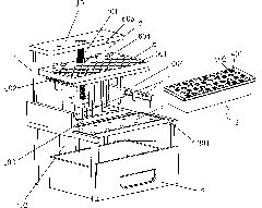
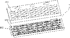
[0030] A fully automatic vacuum test tube decapping machine, such as Figure 1-6 As shown, it includes a frame 1, a test tube cap collection box 2, a cap removal frame 6, a cap removal frame lifting drive device and a test tube box 4, and the test tube cap collection box 2 is arranged at the bottom of the frame 1, and a test tube box is arranged in the middle of the frame 1 The positioning device and the test tube box transfer device, the test tube box positioning device is arranged on the rear side of the middle part of the frame 1, the test tube box transfer device is arranged on the front side of the frame 1 middle part, and the cap removal frame 6 is arranged above the test tube box positioning device, and the cap removal frame lifts The driving device is installed on the rear side of the frame 1, and the test tube box 4 is placed on the test tube box transfer device. Extrusion hole 402, a rubber sleeve or rubber ring 403 is provided in the cylindrical hole 401, the inner ...


PUM


Abstract

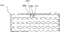
The invention discloses a full-automatic vacuum test tube uncapping machine, which comprises a frame, a test tube cap collection box, an uncapping stand, an uncapping stand lifting drive device, a test tube box, a test tube box transferring device and a test tube box positioning device, wherein cylindrical holes for accommodating test tubes and extrusion holes are distributed on the test tube box; a rubber cover is arranged in each cylindrical hole; each cylindrical hole is correspondingly provided with an extrusion block; one end of the extrusion block contacts a rubber ring, while the other end stretches into each extrusion hole; annular holes which can be inserted by the test tubes are distributed on the uncapping stand; a horizontally arranged uncapping plate is arranged in the uncapping stand; uncapping holes are formed on the uncapping plate; the uncapping plate is driven by an uncapping plate drive device and can move left and right in a horizontal direction in the uncapping stand; a push rod is arranged at the bottom of the uncapping stand; and the push rod comprises a conical part and a cylindrical part. The full-automatic vacuum test tube uncapping machine has the advantages of small volume, simple structure, high efficiency, strong practicability, high safety, low manufacturing cost and the like.

Description

technical field [0001] The invention relates to a cap removing device for a vacuum test tube. Background technique [0002] As a medical clinical test, it is the most common way to collect blood as a test sample with a vacuum test tube. After collecting blood with a vacuum test tube, there is still a certain negative pressure in the vacuum test tube, and the tight fit between the test tube cover and the test tube wall makes the test tube cover (or test tube cap) still firmly fixed on the test tube. It takes a lot of force to pull off the test tube cap. When vacuum test tubes are used in large quantities, the work of opening the test tube cover becomes relatively heavy manual labor. In the process of vigorously opening the test tube cover, there will also be internal oscillations in the test tube, which may disperse the centrifuged samples, affect some test results, and have certain technical requirements for the operator. Vigorously opening the test tube cap may also brea...

Claims


Application Information

Patent Timeline
IPC IPC(8): B67B7/02
Inventor 钟鄂绘邱文斌黄斌麦自强
Owner 珠海丰炎科技有限公司
Learn More