Combined steel pipe-encased concrete type buckling-restrained brace member
A technology of anti-buckling bracing and combining steel pipes, which is used in building components, shock-proofing and other directions, can solve the problem of damage to the production cycle of special soft material boards without bonding material boards, high processing cost of in-line support cores, and inability to ensure low-cycle fatigue performance. and other problems, to achieve the effect of solving local damage and displacement of soft materials, easy control of finished product quality, and avoiding residual tensile stress
- Summary
- Abstract
- Description
- Claims
- Application Information
AI Technical Summary
Problems solved by technology
Method used
Image

Examples
specific Embodiment approach 1
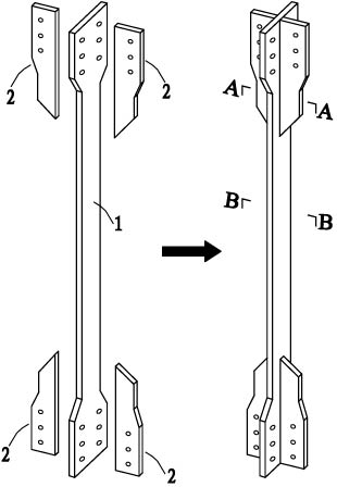
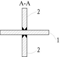
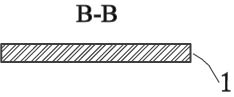
[0008] Specific implementation mode one: as Figure 6-16 As shown, the anti-buckling support member of this embodiment includes an inline support inner core 6 and an outer restraint member 7, and the outer restraint member 7 is composed of two rectangular steel pipes 7-1, four channel steels 7-2, two second A backing plate 8 and two second backing plates 9 are formed, and the two ends of each rectangular steel pipe 7-1 are located on the pipe wall of the long side and each has a rectangular gap 7 along the height direction of the rectangular steel pipe 7-1. -4, two rectangular gaps 7-4 are arranged opposite each other, one side end face of each channel steel 7-2 is an inclined plane, and each channel steel 7-2 is fixed in the rectangular gap 7-4 by partial spot welding, the channel steel The maximum height of 7-2 is the same as the height of the rectangular gap 7-4, and the opening of each channel steel 7-2 faces the outside of the rectangular steel pipe 7-1, forming a gap bet...
specific Embodiment approach 2
[0010] Specific implementation mode two: as Figure 6As shown, each variable cross-section stiffener 6-2 in this embodiment is sequentially composed of a first support plate 6-2-1, a transition plate 6-2-2 and a connecting plate 6-2-3 and is integrated, The width and thickness of the connecting plate 6-2-3 match the groove depth and groove width of the channel steel 7-2, and the cross-sectional area of the connecting plate 6-2-3 is smaller than that of the transition plate 6-2-2 Cross-sectional area, the cross-sectional area of the transition plate 6-2-2 is smaller than the cross-sectional area of the first support plate 6-2-1, the outer surface of the transition plate 6-2-2 is a slope, and the inner core is supported in a straight line 6 There is no need for non-bonding treatment on the surface, and there is no need to paste soft materials on the support inner core to reserve axial compression space. Other components and connections are the same as those in the first e...
specific Embodiment approach 3
[0011] Specific implementation mode three: as Figure 6-Figure 13 , Figures 17-19 As shown, the anti-buckling support member of this embodiment includes an inline support inner core 6 and an outer restraint member 7, and the outer restraint member 7 is composed of two rectangular steel pipes 7-1, four channel steels 7-2, two pieces of the first Three backing plates 10, many pairs of bolt seats 11 and a plurality of bolts 12 are formed, and each rectangular steel pipe 7-1 has two ends on the long-side pipe wall along the height direction of the rectangular steel pipe 7-1. Rectangular gap 7-4, two rectangular gaps 7-4 are arranged opposite each other, one side end face of each channel steel 7-2 is a slope, and each channel steel 7-2 is fixed in the rectangular gap 7-4 by partial spot welding , the maximum height of the channel steel 7-2 is the same as the height of the rectangular notch 7-4, the opening of each channel steel 7-2 faces the outside of the rectangular steel pipe ...
PUM
 Abstract
Description
Claims
Application Information
 - R&D
- Intellectual Property
- Life Sciences
- Materials
- Tech Scout
- Unparalleled Data Quality
- Higher Quality Content
- 60% Fewer Hallucinations
Browse by: Latest US Patents, China's latest patents, Technical Efficacy Thesaurus, Application Domain, Technology Topic, Popular Technical Reports.
© 2025 PatSnap. All rights reserved.Legal|Privacy policy|Modern Slavery Act Transparency Statement|Sitemap|About US| Contact US: help@patsnap.com