Anti-vibration actuator and lens unit/camera equipped therewith

A lens unit and actuator technology, which is applied in the field of camera devices and lens units, can solve the problems of not being able to directly control the rotation and movement of the lens used for image stabilization, and the reduction of image stabilization accuracy, and achieve large driving force, suppression of rotation and movement, and simple structure Effect

Inactive Publication Date: 2010-08-11
TAMRON
View PDF2 Cites 14 Cited by
  • Summary
  • Abstract
  • Description
  • Claims
  • Application Information

AI Technical Summary

Problems solved by technology

[0011] However, in the actuator described in Japanese Patent Application Laid-Open No. 2008-122531, since the driving force of each linear motor is directed in the radial direction, there is a problem that the rotational movement of the image stabilization lens cannot be directly controlled.
Therefore, along with the translational movement of the image stabilization lens, the image stabilization lens undergoes unnecessary rotational movement, resulting in a decrease in the accuracy of image stabilization.

Method used


Image

  • Anti-vibration actuator and lens unit/camera equipped therewith
  • Anti-vibration actuator and lens unit/camera equipped therewith
  • Anti-vibration actuator and lens unit/camera equipped therewith

Examples


Embodiment Construction

[0042] Hereinafter, embodiments of the present invention will be described with reference to the drawings.

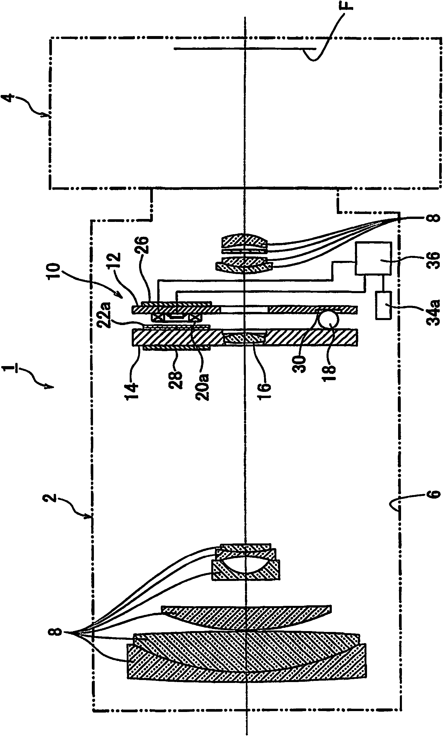
[0043] First, refer to Figure 1 to Figure 8 An imaging device according to an embodiment of the present invention will be described. figure 1 It is a cross-sectional view of the imaging device according to the embodiment of the present invention.

[0044] Such as figure 1 As shown, an imaging device 1 according to an embodiment of the present invention includes a lens unit 2 and an imaging device main body 4 . The lens unit 2 includes a lens barrel 6, a plurality of photographing lenses 8 arranged in the lens barrel, an anti-vibration actuator 10 for moving an image stabilizing lens 16 in a predetermined plane, and a sensor for detecting the lens barrel. The vibration detection parts of 6 vibrations are gyroscopes 34a, 34b ( figure 1 Only 34a) is indicated in .

[0045] The imaging device 1 according to the embodiment of the present invention detects vibrations...


PUM


Abstract

To provide an anti-vibration actuator with which a high drive force can be obtained without increasing size. The present invention is an anti-vibration actuator, including a fixed portion, a movable portion, movable portion support means, first drive means having a first drive magnet and coil; second drive means having a second drive magnet and coil; third drive means having a third drive magnet and coil; first, second, and third position detection elements for detecting the positions of each drive magnet; and a control portion for moving the movable portion to a specified position; wherein the first and second position detection elements are disposed within a region diagonally opposed to the region in which the third drive means is positioned, from among four regions partitioned by the lines of action of the drive forces of the first and second drive means.

Description

technical field [0001] The present invention relates to an anti-vibration actuator (actuator), in particular to an anti-vibration actuator for moving an image stabilization lens in a plane perpendicular to the optical axis of the image stabilization lens, and an anti-vibration actuator having the anti-vibration actuator. Actuator lens unit, camera device. Background technique [0002] An actuator is described in JP 2006-106177 A (Patent Document 1). Figure 11 Indicates the approximate structure of the actuator. Such as Figure 11 As shown, the actuator 110 includes a fixed part 112 and a movable part 114 , and the movable part 114 is supported by three steel balls 118 so that the movable part 114 can move in translation and rotate relative to the fixed part 112 . In addition, the movable part 114 is driven by three linear motors composed of three sets of driving coils 120 and driving magnets 122 . [0003] Lines of action of the driving forces generated by the three linea...

Claims


Application Information

Patent Timeline
Patent Type & Authority Applications(China)
IPC IPC(8): G03B5/00H04N5/232H02K33/18
CPCG03B2205/0015G03B2205/0007G02B27/646G03B5/00
Inventor 阿久津敏宪
Owner TAMRON
Why Eureka
Try Eureka