Screw compressor

A screw compressor, screw technology, applied in the direction of rotary piston machinery, mechanical equipment, machine/engine, etc., can solve the problems of compression torque pulsation of twin or single screw compressor, reduction of single noise of axial fan, etc. Achieve the effect of avoiding switching, reducing compression torque fluctuation, and easy design

Active Publication Date: 2012-11-14
DAIKIN IND LTD
View PDF3 Cites 0 Cited by
  • Summary
  • Abstract
  • Description
  • Claims
  • Application Information

AI Technical Summary

Problems solved by technology

However, in this case, since the compression timing itself is not changed, the maximum torque timing of the torque fluctuation is only slightly shifted, and the minimum torque timing is not shifted, and there is a problem that resonance due to torque ripple occurs.
[0010] In addition, by setting the pitches of the blades of the rotating fan to unequal pitches, the device for dispersing the frequency of the blowing air pulsation is also known (see Japanese Patent Laid-Open No. 2003-42094, etc.), but this technology relates to axial flow fans. The single-screw noise reduction makes it difficult to solve the compression torque pulsation that is the main cause of vibration excitation of twin or single-screw compressors

Method used


Image

  • Screw compressor
  • Screw compressor
  • Screw compressor

Examples


no. 1 approach

[0098] (Features of the first embodiment)

[0099] (1)

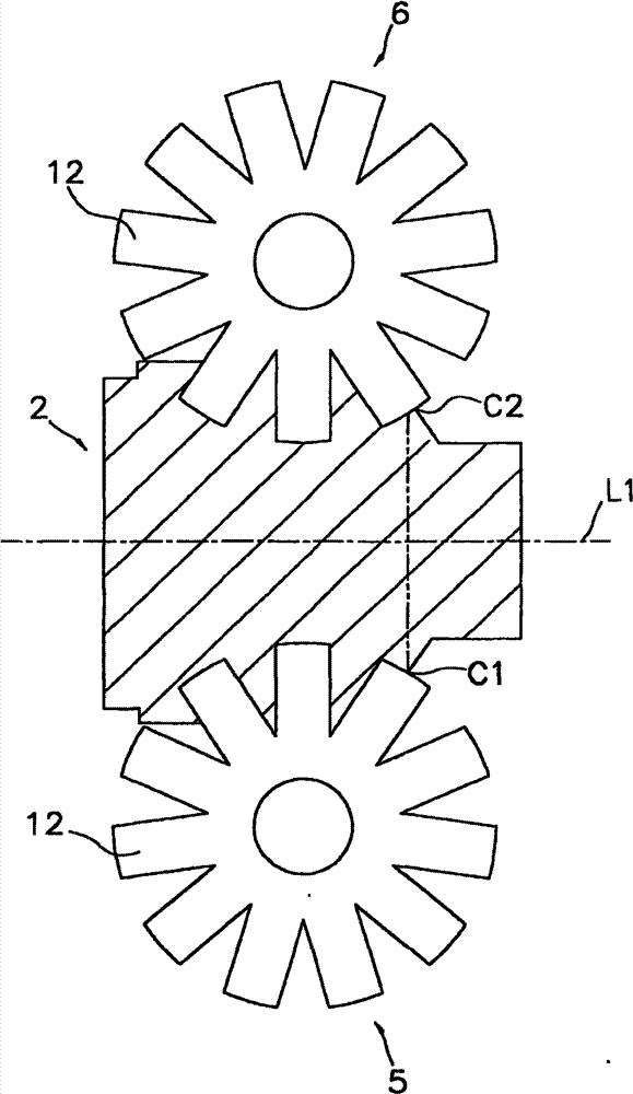
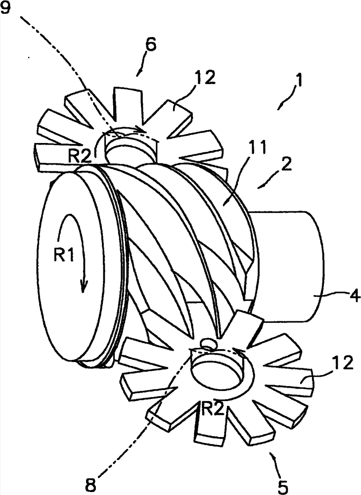
[0100] In the single screw compressor 1 of the first embodiment, at least one tooth 12 (eg, Figure 4 The teeth 12 a 1 , 12 a 2 , 12 b 1 , and 12 b 2 of (a) are arranged unevenly with respect to the other teeth 12 in the circumferential direction of the rotation shafts 8 , 9 . In addition, the plurality of helical grooves 11 of the screw rotor 2 are arranged in the circumferential direction of the rotary shaft 4 so as to be able to mesh with the plurality of teeth 12 .

[0101] Accordingly, it is possible to significantly reduce the compression torque variation and the resulting torque ripple that occur in the conventional screw in which grooves and teeth are arranged at equal intervals. As a result, it is possible to reduce noise and vibration accompanying compression torque fluctuations. Furthermore, it is possible to reduce noise and vibration accompanying suction and discharge flow rate fluctuations and pressure p...

no. 2 approach

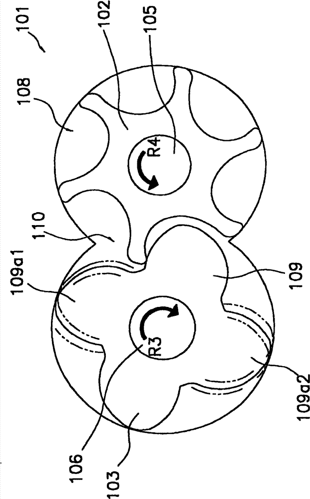
[0136] Next, the twin-screw compressor 101 which is one embodiment of the screw compressor of the present invention will be described with reference to the drawings.

[0137] (Structure of twin-screw compressor 101)

[0138] Figure 7-8 The illustrated twin-screw compressor 101 includes: a female rotor 102, a male rotor 103, a housing 104 for accommodating the female rotor 102 and the male rotor 103, a first rotating shaft 105 serving as the rotating shaft of the female rotor 102, and a male rotor 103. The second rotating shaft 106 of the rotating shaft, and the rolling bearings 107a, 107b, 107c, and 107d that rotatably support the first rotating shaft 105 and the second rotating shaft 106 inside the housing 104 .

[0139] Figure 7-8 The illustrated female rotor 102 and male rotor 103 are arranged horizontally, but they may also be arranged vertically.

[0140] Here, the female rotor 102 corresponds to the first engaging body of the present invention. In addition, the mal...


PUM


Abstract

A screw compressor in which noise and vibration caused by a variation in compression torque are effectively reduced. The screw compressor (1) has a first meshing body (2) and second meshing bodies (5, 6). The first meshing body (2) has helical grooves (11) around a first rotating shaft (4). The second meshing bodies (5, 6) have projections (12) or ridges formed around second rotating shafts (8, 9). At least one projection (12) or ridge of each second rotating shaft (8, 9) is placed irregularly in the circumferential direction with respect to the other projections (12) or ridges. The helical grooves (11) are arranged in the circumferential direction in the first rotating shaft (4) so as to be able to mesh with the projections (12) or ridges.

Description

technical field [0001] The present invention relates to screw compressors. Background technique [0002] Conventionally, various compressors have been proposed for compressing a compression medium such as a refrigerant of a refrigerator, but among them, a screw compressor has lower vibration and noise than a reciprocating compressor and is used in various applications. [0003] The twin-screw compressor described in Patent Document 1 includes: a female rotor having a helical groove, a male rotor having a helical ridge that engages with the helical groove of the female rotor, and a housing for accommodating the female rotor and the male rotor. body. Inside the casing, the male and female rotors rotate while engaging with each other, whereby the compressed medium is compressed in the operating chamber (compression chamber) formed in the spiral groove, and then discharged from the discharge port of the casing. [0004] In the twin-screw compressor described in Patent Document...

Claims


Application Information

Patent Timeline
Patent Type & Authority Patents(China)
IPC IPC(8): F04C29/06F04C18/16F04C29/00
CPCF04C18/084F04C29/06F04C18/52F04C29/0021F04C2270/12F04C2270/13
Inventor 增田正典M·A·侯赛因福永刚
Owner DAIKIN IND LTD
Why Eureka
Try Eureka