Thin film type solar cell and method for manufacturing the same

一种太阳能电池、薄膜型的技术,应用在太阳能电池领域,能够解决薄膜型太阳能电池过程复杂等问题,达到精确划分、防止问题、防止电阻增大的效果

Active Publication Date: 2012-11-07
JUSUNG ENG
View PDF0 Cites 0 Cited by
  • Summary
  • Abstract
  • Description
  • Claims
  • Application Information

AI Technical Summary

Problems solved by technology

[0022] Third, the laser scribing process complicates the process of manufacturing thin-film solar cells
In addition, it is difficult to continuously perform the laser scribing process under atmospheric conditions and other processes under vacuum conditions

Method used


Image

  • Thin film type solar cell and method for manufacturing the same
  • Thin film type solar cell and method for manufacturing the same
  • Thin film type solar cell and method for manufacturing the same

Examples


no. 1 example

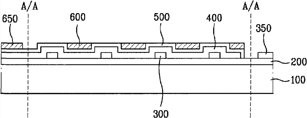
[0077] figure 2 is a sectional view illustrating the thin film type solar cell according to the first embodiment of the present invention.

[0078] Such as figure 2 As shown, the thin film solar cell according to the first embodiment of the present invention includes: a substrate 100 , a front electrode layer 200 , an auxiliary electrode 300 , a semiconductor layer 400 , a transparent conductive layer 500 and a back electrode 600 .

[0079] Here, the substrate 100 may be formed of glass or transparent plastic. The transparent conductive layer 200 is formed on the substrate 100, wherein the transparent conductive layer 200 can be made of such as ZnO, ZnO:B, ZnO:Al, ZnO by sputtering or MOCVD (Metal Organic Chemical Vapor Deposition, Metal Organic Chemical Vapor Deposition) method. :H, SnO 2 , SnO 2 : F or ITO (indium tin oxide) and other transparent conductive materials.

[0080] In addition, the front electrode layer 200 corresponds to the incident surface of the sun's ...

no. 2 example

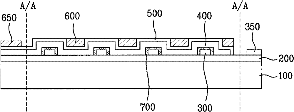
[0105] image 3 is a sectional view illustrating a thin film type solar cell according to a second embodiment of the present invention.

[0106] Except that the insulating layer 700 is additionally provided, the thin-film solar cell according to the second embodiment of the present invention is structurally the same as the thin-film solar cell according to the first embodiment of the present invention, therefore, the The same reference numerals are used throughout the drawings to denote the same or similar parts, and detailed descriptions of the same parts are omitted.

[0107] The thin film type solar cell according to the second embodiment of the present invention additionally includes an insulating layer 700 covering the auxiliary electrode 300 , that is, the insulating layer 700 is formed on side and upper surfaces of the auxiliary electrode 300 . More specifically, the insulating layer 700 is formed on Figure 8 On the side surfaces and upper surfaces of the first auxil...

no. 3 example

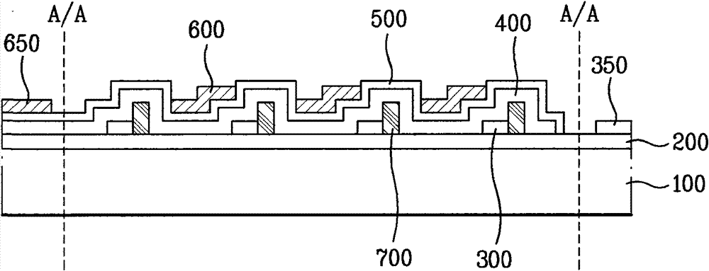
[0112] Figure 4 is a cross-sectional view illustrating a thin film type solar cell according to a third embodiment of the present invention.

[0113] Except that an insulating layer 700 is additionally provided, the thin-film solar cell according to the third embodiment of the present invention is structurally the same as the thin-film solar cell according to the first embodiment of the present invention, therefore, all The same reference numerals are used in the drawings to denote the same or similar parts, and detailed descriptions of the same parts are omitted.

[0114] The thin film type solar cell according to the third embodiment of the present invention additionally includes an insulating layer 700 , wherein the insulating layer 700 is formed on one side of the auxiliary electrode 300 . More specifically, the insulating layer 700 is formed on Figure 8 One side of the first auxiliary electrode 310 shown in A to 8D, wherein the insulating layer 700 is higher than the ...


PUM


Abstract

A thin film type solar cell and a method for manufacturing the same is disclosed, which can overcome various problems caused by a related art laser-scribing procedure since the thin film type solar cell is divided into a plurality of sub-cells through the use of auxiliary electrode or partition wall, the thin film type solar cell comprising a substrate; a front electrode layer and a cell-dividingpart on the substrate; and a rear electrode on the semiconductor layer.

Description

technical field [0001] The present invention relates to a solar cell, and more particularly, to a thin film type solar cell suitable for minimizing the resistance of a front electrode. Background technique [0002] Solar cells with semiconducting properties convert light energy into electricity. [0003] The structure and principle of the solar cell according to the prior art will be briefly explained below. A solar cell is formed in a PN junction structure in which a positive (P) type semiconductor and a negative (N) type semiconductor form a junction. When sunlight is incident on the solar cell having the PN junction structure, holes (+) and electrons (-) are generated in the semiconductor due to the energy of the sunlight. Under the action of the electric field generated in the PN junction region, the holes (+) drift to the P-type semiconductor, and the electrons (-) drift to the N-type semiconductor, thereby generating electric power and appearing a potential. [0004...

Claims


Application Information

Patent Timeline
Patent Type & Authority Patents(China)
IPC IPC(8): H01L31/042
CPCH01L31/1804H01L27/1425H01L31/022433H01L31/022425H01L31/03921Y02E10/548Y02E10/547H01L31/0463Y02P70/50
Inventor 洪震金宰湖金桢植
Owner JUSUNG ENG
Why Eureka
Try Eureka