Multicore cable connector

A kind of technology of multi-core cable and connector

Inactive Publication Date: 2010-08-11
3M INNOVATIVE PROPERTIES CO
View PDF0 Cites 18 Cited by
  • Summary
  • Abstract
  • Description
  • Claims
  • Application Information

AI Technical Summary

Problems solved by technology

Therefore, in the part of the wiring pattern where the coating is cut off in each signal line and its end is soldered to the substrate, the exposed signal line is arranged adjacent to another signal line, which sometimes causes impedance i

Method used


Image

  • Multicore cable connector
  • Multicore cable connector
  • Multicore cable connector

Examples


Embodiment Construction

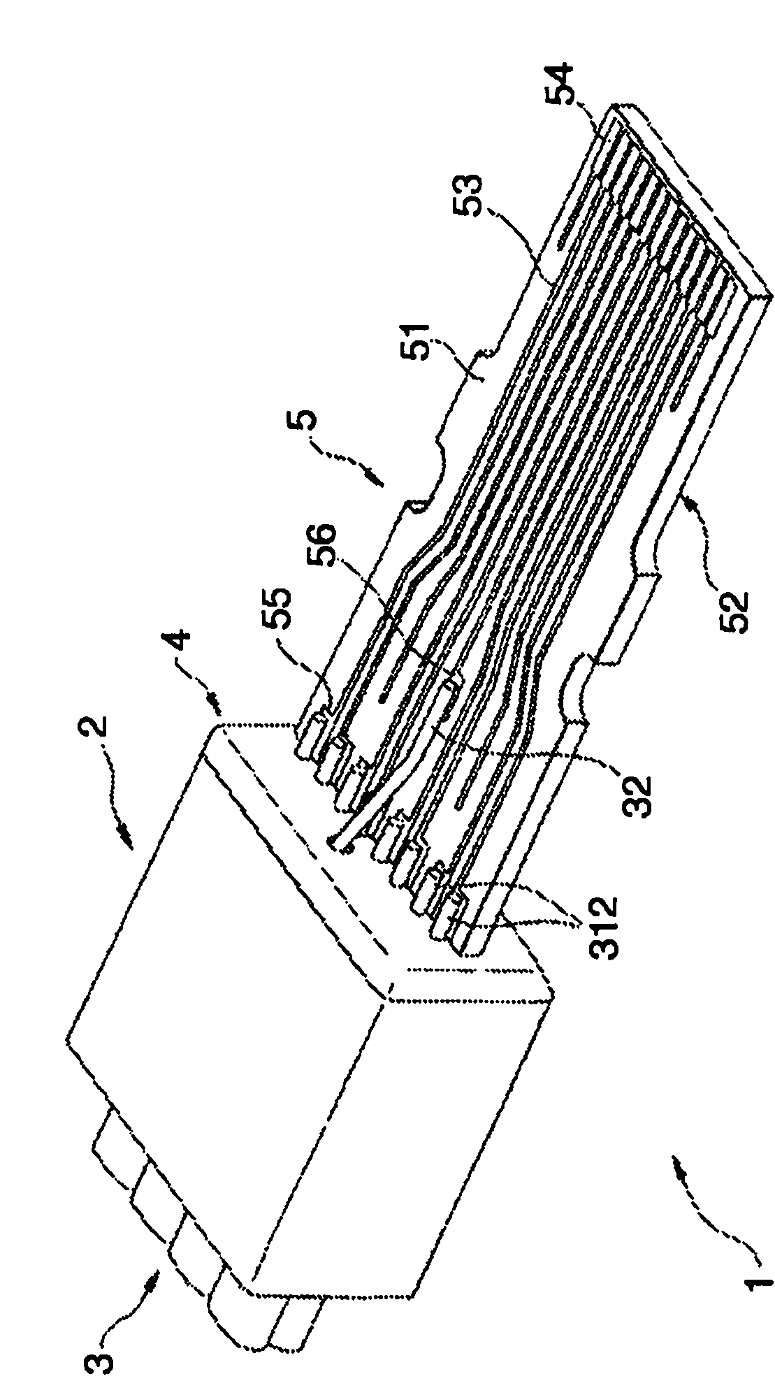
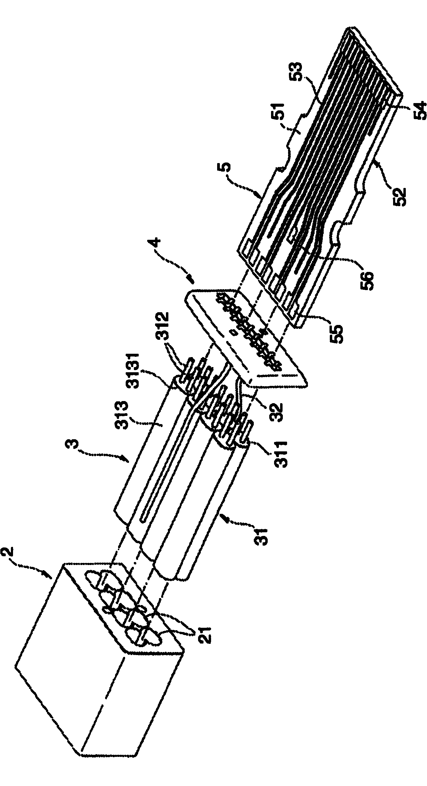
[0017] figure 1 is a perspective view showing an internal structure of a multi-core cable connector according to a preferred embodiment of the present invention, figure 2 It is a schematic diagram of its disassembly and assembly. A multi-core cable connector (hereinafter simply referred to as a connector) 1 includes a cable fixing member 2, bundled cables 3 fixed in the cable fixing member 2, and an alignment plate for aligning signal wires included in the bundled cables 3 4 and the substrate 5 electrically connected to the signal lines of the bundled cables 3 . Although not shown, connector 1 has a cover figure 1 The housing of the entire internal structure shown in , the housing is shaped to cooperate with a receptacle (not shown) electrically connected to the connector 1 .

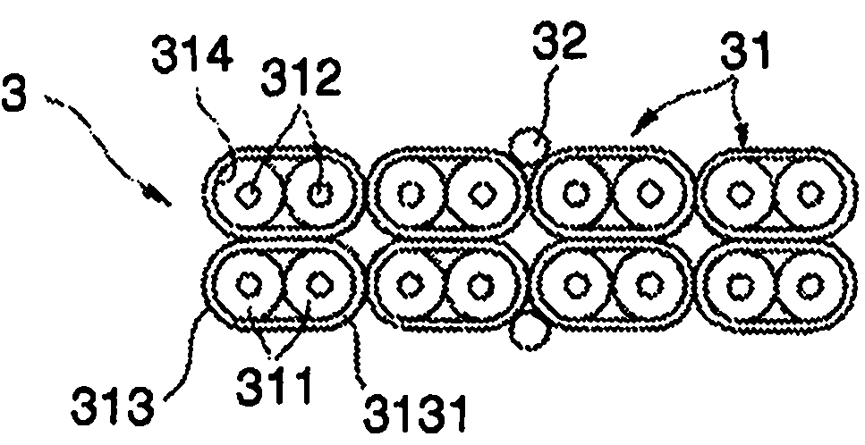
[0018] Such as image 3 As shown, the bundled cable 3 comprises a plurality (eight in the illustrated case) of single cables 31 each having two signal wires 312 respectively concentrically covered ...


PUM


Abstract

To provide a multicore cable connector in which alignment of signal lines of a cable and soldering of the signal lines to a wiring pattern of a substrate are facilitated, and impedance mismatch on the substrate is minimized. A multicore cable connector 1 includes a cable fixing member 2, an aggregate cable 3 accommodated in cable fixing member 2, an aligning plate 4 for aligning signal lines 312 included in aggregate cable 3, and a substrate 5 formed with a wiring pattern 53 conductively connected to signal lines 312 of aggregate cable 3.

Description

technical field [0001] The present invention relates to a multi-core cable connector with multiple signal lines, or specifically, to a multi-core cable connector for high-speed transmission. Background technique [0002] With the development of high-speed transmission, more and more cable connectors including a greater number of signal lines than in the prior art have been gradually used in personal computers and mass storage devices. On the other hand, the cable connector is required to be compact. Therefore, a plurality of signal lines are arranged in the connector at high density. In such cable connectors, the distance between the signal lines is so short that it is necessary to precisely conductively connect each signal line to the substrate by soldering or the like. [0003] For example, Japanese Unexamined Patent Publication No. 2003-109708 discloses a multi-core high-speed signal transmission connector in which "the thickness of the insulating plate is determined in...

Claims


Application Information

Patent Timeline
IPC IPC(8): H01R13/648H01R12/53H01R13/658
CPCH01R9/034H01R12/62H01R13/65914
Inventor 桑原研尔远藤敏郎松冈宏行
Owner 3M INNOVATIVE PROPERTIES CO
Why Eureka
Try Eureka