Commutation device and electric machine

A commutation device and commutator technology, applied in the direction of circuits, current collectors, electrical components, etc., can solve problems such as short circuit, shortened service life of motors, deposition, etc., and achieve the effects of increasing service life, avoiding deposition, and avoiding electrical short circuits

Inactive Publication Date: 2010-08-11
ROBERT BOSCH GMBH
View PDF0 Cites 2 Cited by
  • Summary
  • Abstract
  • Description
  • Claims
  • Application Information

AI Technical Summary

Problems solved by technology

Seen in the direction of rotation of the commutator, this wear debris deposits in front of the brush elements, which leads to pre-commutation and thus to a shortened service life of motors equipped wit

Method used


Image

  • Commutation device and electric machine
  • Commutation device and electric machine
  • Commutation device and electric machine

Examples


Example Embodiment

[0025] In the drawings, identical parts and parts having the same function are designated with the same reference numerals.

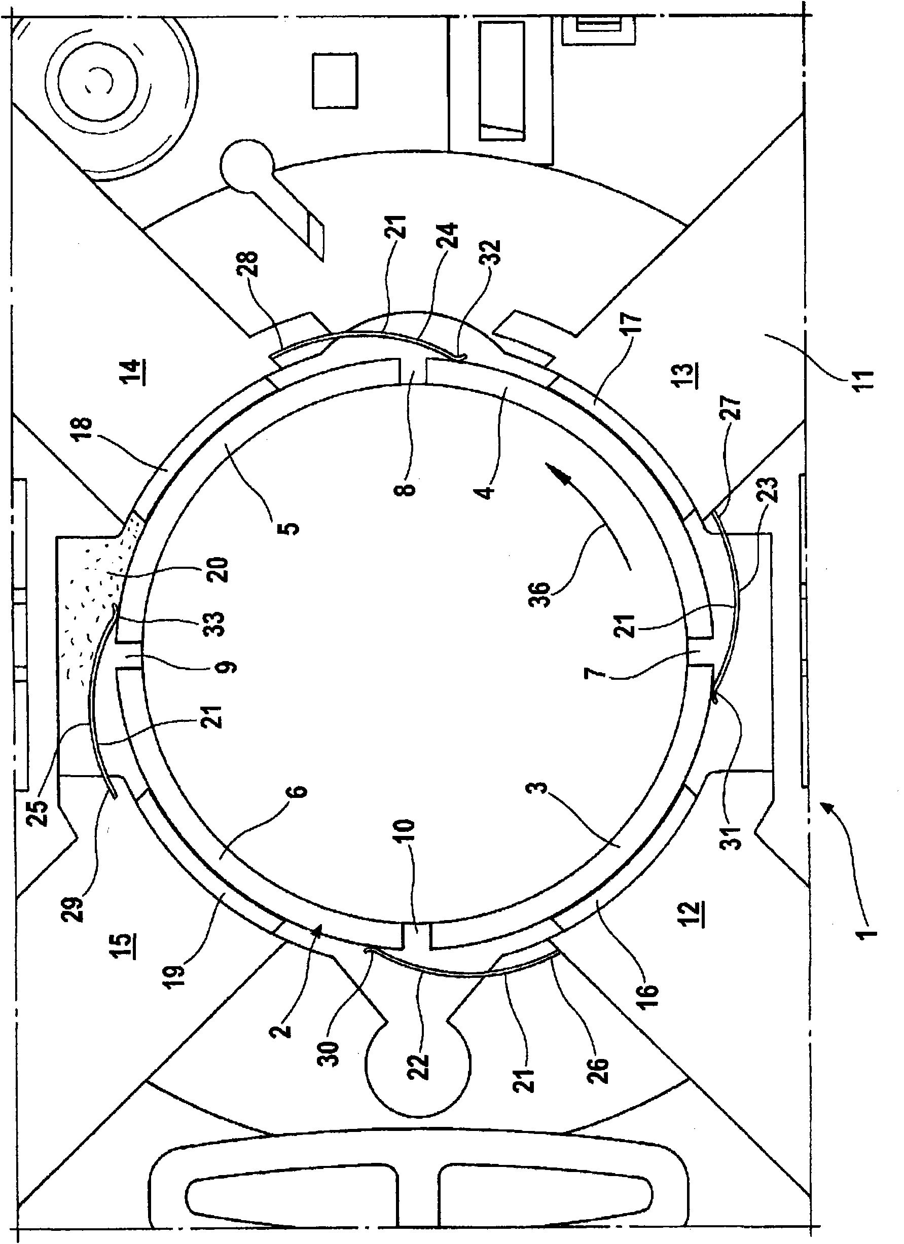
[0026] exist figure 1 A commutation device 1 for an electric machine is shown. The commutation device 1 comprises a commutator 2 which is arranged non-rotatably on an armature shaft, not shown, which stands vertically on the plane of the drawing. In the embodiment shown, the commutator 2 comprises four foils 3, 4, 5, 6 made of copper which are arranged side by side in the circumferential direction. The laminations 3 , 4 , 5 , 6 are electrically conductively connected to the armature windings of the armature lamination stack, not shown. Air gaps 7, 8, 9, 10 extending in the axial direction are provided between each two adjacent sheets to keep the sheets 3, 4, 5, 6 electrically insulated from each other.

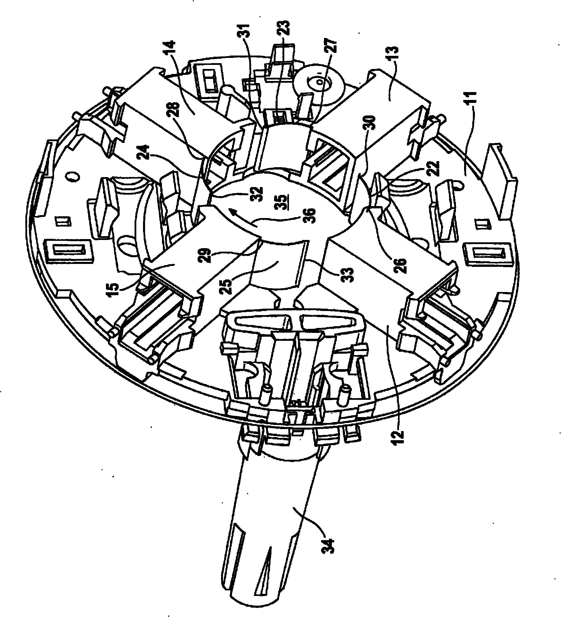
[0027] The commutator 2 is arranged inside a brush element holder 11, which in this exemplary embodiment has four sleeves 12, 13, 14, 15 that are even...


PUM


Abstract

The invention relates to a commutation device (1) having a rotatable commutator (2) and at least one grinding element (16, 17, 18, 19) contacting the commutator (2). According to the invention, mechanism (21) for removing abrasion debris (20) occurring during commutation are provided. The invention further relates to an electric machine having a commutation device (1) of said kind. The mechanism includes at least one non-conductive spring (22, 23, 24, 25) clung onto the commutator (2). The spring designed as a plate spring is fixed onto a holder for the grinding elements by means of the end portion of the spring facing away from the commutator and is clung onto the commutator by means of the free end portion of the spring.

Description

technical field [0001] The invention relates to a commutation device according to the preamble of claim 1 and to an electric machine, in particular an electric motor or a generator, according to claim 16 . Background technique [0002] In electrotechnical terms, a device for commutating the current in an electric motor is called a commutation device. Current commutation produces a rotating or migrating current relative to the armature winding. The known commutation device comprises a commutator located non-rotatably on an armature shaft, which commutator has a plurality of lamellae arranged side by side in the circumferential direction and electrically insulated from each other, said lamellae being connected to at least two electrical The brush elements are in electrical contact. Wear debris, usually carbon dust, is produced by the constant friction between the stationary brush elements and the rotationally driven commutator. Seen in the direction of rotation of the commu...

Claims


Application Information

Patent Timeline
IPC IPC(8): H01R39/38
CPCH01R39/38H01R39/045
Inventor D·克卢姆普E·辛尔A·西巴克
Owner ROBERT BOSCH GMBH
Why Eureka
Try Eureka