Hydraulic buffer stopper

A hydraulic buffer and hydraulic buffer technology, applied in the direction of forced railway stopper, railway car body parts, transportation and packaging, etc., can solve the problems of low energy and damaged coupler, and achieve the effect of ensuring safety and preventing crashes.

Inactive Publication Date: 2010-08-18
沈阳中铁安全设备有限责任公司
View PDF0 Cites 14 Cited by
  • Summary
  • Abstract
  • Description
  • Claims
  • Application Information

AI Technical Summary

Problems solved by technology

Although the buffer head is equipped with a buffer rubber plate, the energy absorbed is small, and there is a danger of crashing the coupler when the impact force is large

Method used


Image

  • Hydraulic buffer stopper
  • Hydraulic buffer stopper
  • Hydraulic buffer stopper

Examples


Embodiment 1

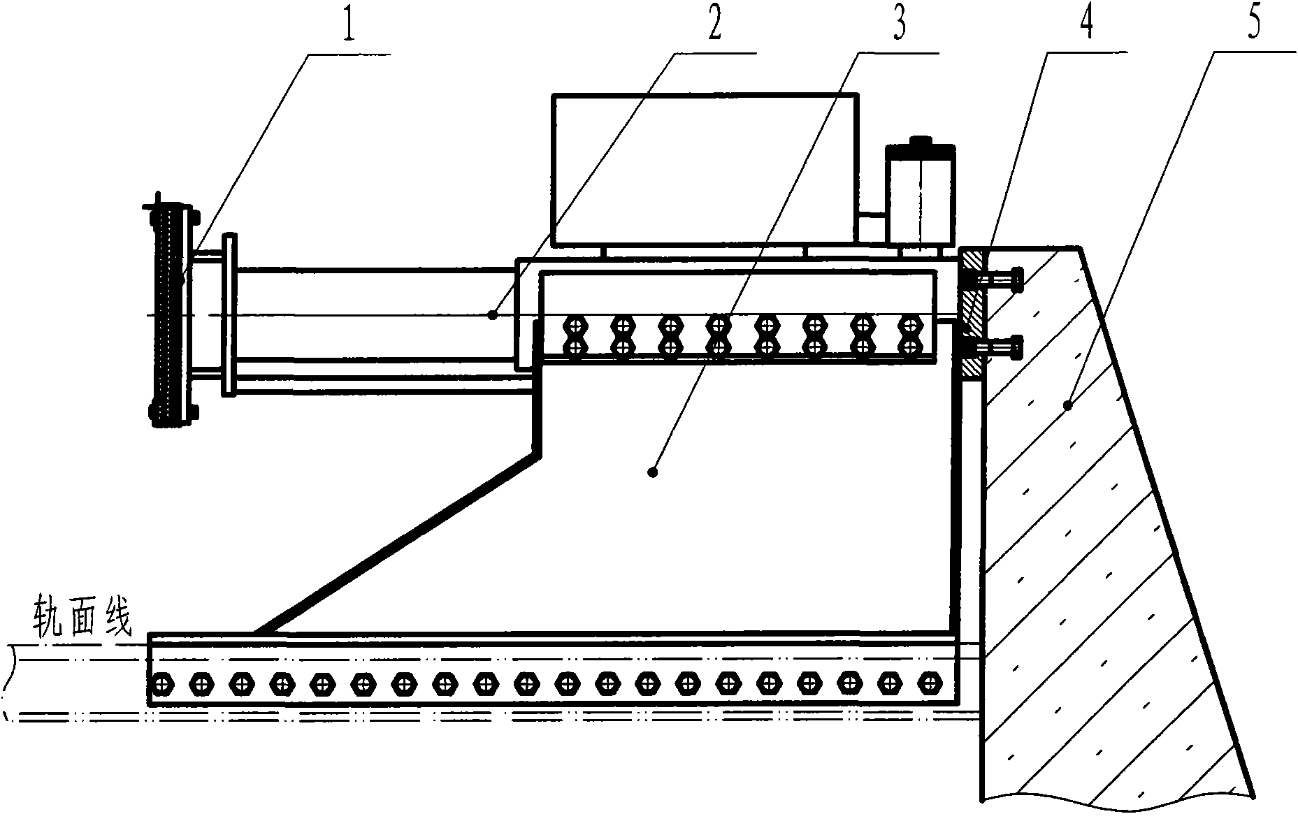
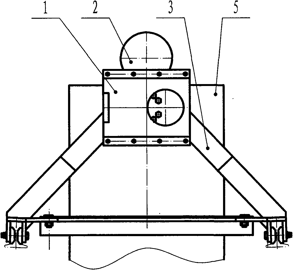
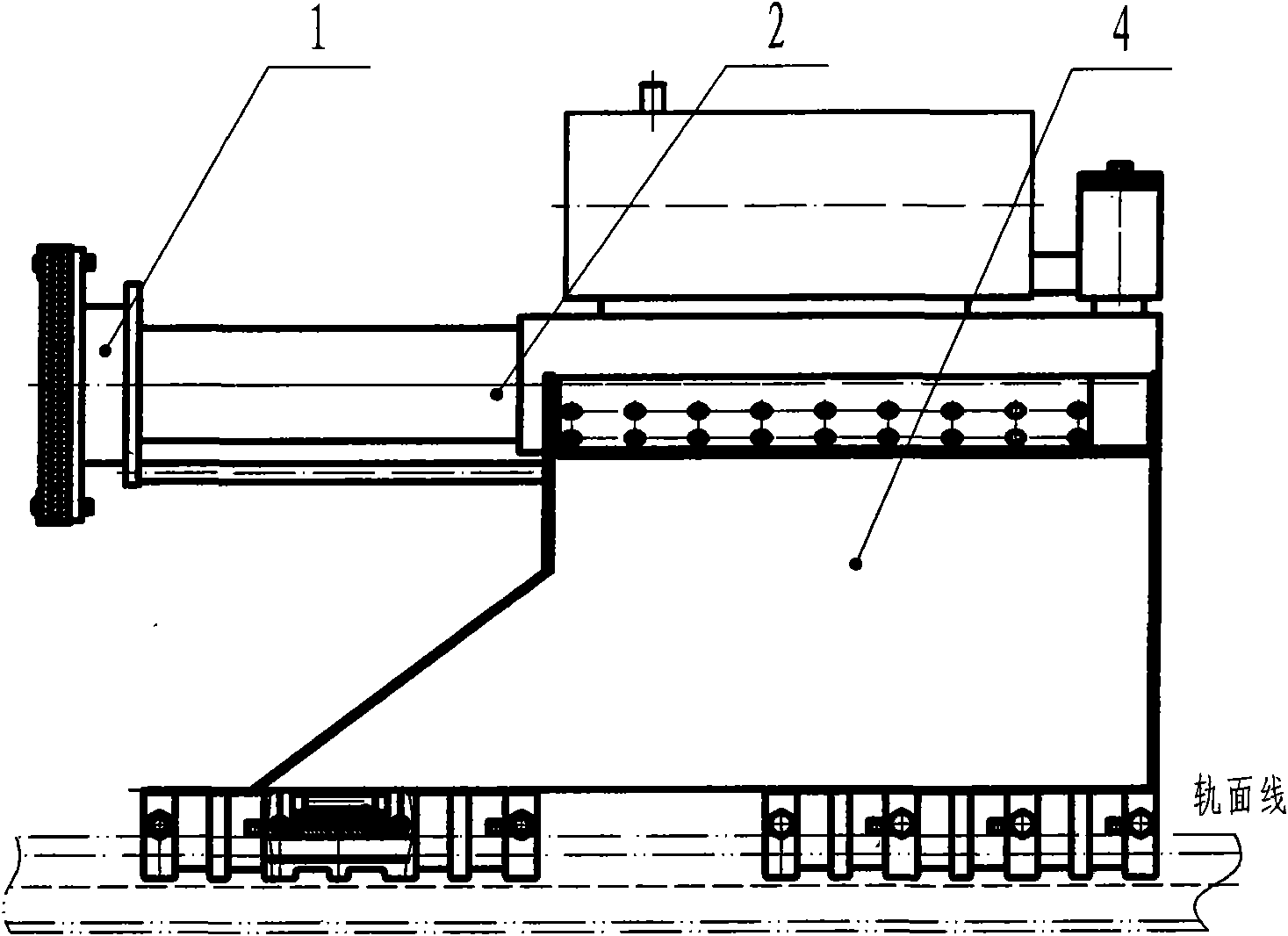
[0042] Embodiment 1: as figure 1 , figure 2 As shown, the fixed hydraulic buffer car stop is composed of a buffer head 1, a hydraulic buffer assembly 2, a fixed bracket 3, a buffer seat 4 and a retaining wall 5. The buffer head 1 and the plunger of the hydraulic buffer assembly 2 are fastened and connected with bolts, and the connecting plates 2-14 on both sides of the oil cylinder of the hydraulic buffer assembly 2 and the left and right support arms 3-2 of the fixed bracket 3 are connected with bolts, nuts and The spring washer is fastened and connected, the rear end of the hydraulic buffer assembly 2 is connected with the retaining wall 5 through the buffer seat 4 with bolts, and the left and right support arms 3-2 of the fixed bracket 3 are connected with the rail transit line with bolts, nuts and spring washers. The basic rail is connected, and when the quality of the rolling train group is small and the speed is low, retaining wall 5 may not be established.

[0043] l...

Embodiment 2

[0051] Embodiment 2: Another hydraulic shock absorber assembly such as Figure 21 , Figure 22 Shown: consisting of plunger end cover 1', left spring seat 2', plunger body 3', return spring 4', cylinder cap tube 5', bolt 6', spring washer 7', nut 8', cylinder cap method Lan 9', oil cylinder flange 10', oil cylinder pipe 11', right spring seat 12', oil cylinder end cover 13', oil cylinder support main board 14', oil cylinder support horizontal plate 15', oil cylinder connecting plate 16', oil tank connecting plate 17 ', fuel tank front cover 18', fuel tank pipe 19', vent pipe 20', oil return pipe 21', oil pipe 22', elbow 23', pressure valve end cover 24', pressure valve spring 25', pressure valve 26', Pressure valve housing 27', oil tank flanged end cover 28', sealing ring 29', spring washer 30', bolt 31', damping hole 32', union 33', tee 34', cylinder left vertical rib 35 ', oil cylinder right vertical rib 36 ', bolt 37 ', spring washer 38 ' and nut 39 ' form. The plunger b...

Embodiment 3

[0052] Embodiment 3: Another hydraulic buffer assembly such as Figure 23 Shown: Air storage tank 1″, pressure valve assembly 2″, oil pipe 3″, check valve 4″, elbow 5″, tee 6″, cylinder end cover 7″, cylinder body 8″, cylinder method Flange 9″, cylinder cap flange 10″, cylinder cap 11″, primary plunger 12″, secondary plunger 13″, N-stage plunger 14″, plunger end cover 15″, traveling wheel 16″, axle 17", Bracket 18", Buffer Head Assembly 19", Oil Wiper 20", O-ring 21", Y-ring 22", Bolt 23", Spring Washer 24", Nut 25" and connection Board 26″ composition. Gas tank 1" is welded with connecting plate 26" and oil cylinder body 8"; pressure valve assembly 2" is welded with oil pipe 3" and installed in gas tank 1", oil pipe 3", elbow 5", three Pass 6" is connected with each other and welded on cylinder body 8", check valve 4" is connected with tee 6" and gas storage tank 1" respectively with oil pipe 3" and elbow 5", and cylinder flange 9" is welded on the cylinder On body 8 ", cy...


PUM


Abstract

The invention discloses a hydraulic buffer stopper, which is a safety device for preventing vehicles from rushing out of line terminal. A buffer head of a fixed hydraulic buffer stopper is tightly and fixedly connected with a plunger bolt of a hydraulic buffer assembly, connecting plates at two sides of an oil cylinder of the hydraulic buffer assembly are connected with supporting arms at the left and right of a fixed bracket via bolts, the rear end of the hydraulic buffer assembly is connected with a retaining wall via a bolt for buffer seat, the retaining wall can be left out in case of low vehicle speed, lower portions of the supporting arms at the left and right of the fixed bracket are connected with a basic rail of the line via bolts, a buffer head of a sliding hydraulic buffer stopper is tightly and fixedly connected with the plunger bolt of the hydraulic buffer assembly, the connecting plates at two sides of the oil cylinder of the hydraulic buffer assembly are connected with supporting arms at the left and right of a sliding bracket, a damper at the lower portion of the sliding bracket is tightly and fixedly clamped on the head of the basic rail of the line via the bolt and is tightly inserted between a spring plate and a friction base via a taper. Such a stopper plays the role of buffering and absorption of impact energy for humping vehicles, thereby guaranteeing shunting safety.

Description

technical field [0001] The hydraulic buffer vehicle stopper is arranged at the end line terminal of a rail line, is a safety device for preventing vehicles from rushing out of the line terminal, and belongs to the technical field of rail traffic safety equipment. Background technique [0002] At present, there are two types of stoppers installed at the terminals of rail transit lines: fixed type and sliding type. The buffer head is used to contact the sliding coupler to prevent the vehicle from running and achieve the purpose of parking. Although the buffer head is provided with a buffer rubber plate, the energy absorbed is small, and when the impact force is large, there is a danger of crashing the coupler. For preventing the generation of above-mentioned hidden danger, design, manufacture a kind of car stopper that has sufficient car resistance, and does not damage the coupler again is the safe production problem demanding prompt solution. Contents of the invention [0...

Claims


Application Information

Patent Timeline
Patent Type & Authority Applications(China)
IPC IPC(8): B61K7/18
Inventor 王梦乔
Owner 沈阳中铁安全设备有限责任公司
Why Eureka
Try Eureka