
Switch control power supply circuit

A power supply circuit and switch control technology, which is applied to battery circuit devices, circuit devices, collectors, etc., can solve problems such as unstable circuit performance, large battery damage, and voltage fluctuations, so as to avoid voltage fluctuations, optimize circuit wiring, and improve The effect of circuit performance

Inactive Publication Date: 2010-08-18
东莞市歌美数码科技有限公司
View PDF4 Cites 4 Cited by
  • Summary
  • Abstract
  • Description
  • Claims
  • Application Information

AI Technical Summary

Problems solved by technology

However, when an external power supply is used for power supply, due to the setting of the circuit, the battery will also be charged at the same time, and the battery will also provide power to external equipment, so the working state of charging and discharging will cause damage to the battery Larger, it is easy to affect the service life of the battery
If a switch is set on the power supply line of the battery, although this switch can cut off the power supply line when the battery is charging, avoiding the working state of discharging while charging, but for the convenience of installation and operation, the switches are all set in the circuit. edge, so that the power supply line must make a bend and pass through the switch before it can be output to the external device
Therefore, it will cause the power supply line to be too long, which will easily cause voltage fluctuations and make the circuit performance unstable.

Method used


Image

  • Switch control power supply circuit
  • Switch control power supply circuit
  • Switch control power supply circuit

Examples


Embodiment Construction

[0018] The present invention will be further described below in conjunction with accompanying drawing:

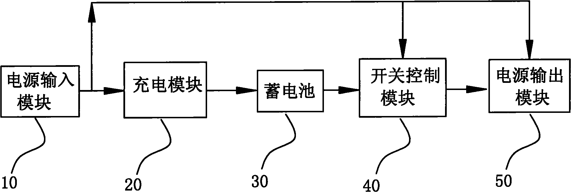
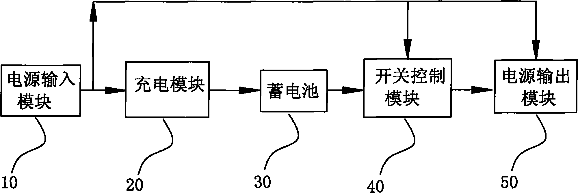
[0019] Such as figure 1 Shown is a structural block diagram of the present invention. In the figure, a switch control power supply circuit includes a power input module 10 , a charging module 20 , a storage battery 30 , a switch control module 40 and a power output module 50 . Wherein, the power input module 10 is respectively connected to the charging module 20 , the switch control module 40 and the power output module 50 , the charging module 20 and the switch control module 40 are jointly connected to the battery 30 , and the switch control module 40 is connected to the power output module 50 .

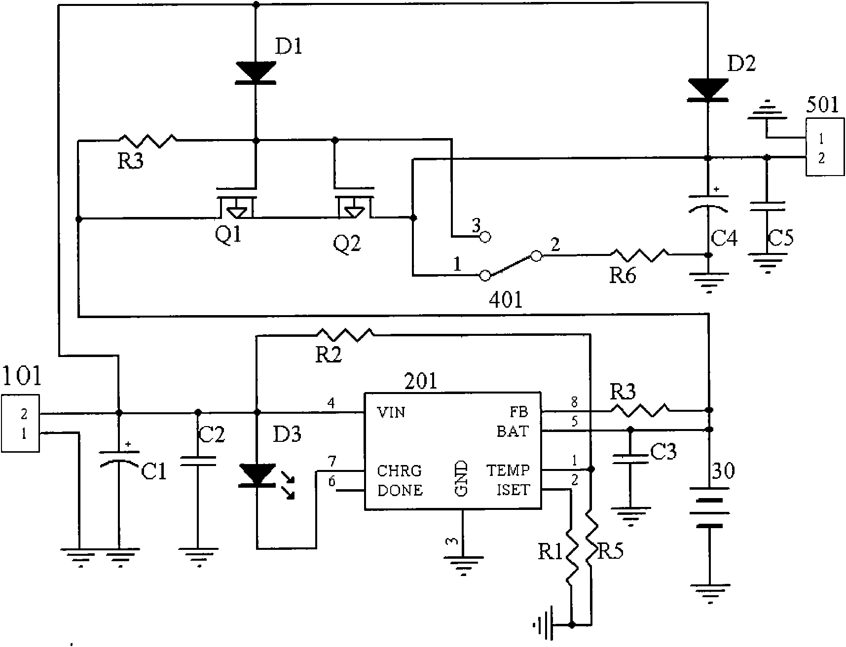
[0020] Such as figure 2 As shown in the specific circuit diagram of the present invention, in the figure, the switch control module 40 includes a diode D1, a transistor Q1, a transistor Q2, a resistor R3, a resistor R6 and a control switch 401; wherein, the anode end of the di...


PUM


Abstract

The invention discloses a switch control power supply circuit, which belongs to a power supply circuit and comprises a power supply input module, a charging module, a storage battery, a switch control module and a power supply output module. In the switch control module, the anode of a diode D1 is connected with the power supply input module and the power supply output module, while the cathode is connected with one end of a resistor R3, the base electrodes of a triode Q1 and a triode Q2 and the third pin of a control switch; the other end of the resistor R3 and the collector electrode of the triode Q1 are connected with the anode of the storage battery and the charging module; the emitting electrode of the triode Q1 is connected with the emitting electrode of the triode Q2; and the collector electrode of the triode Q2 is connected with the first pin of the control switch and the power supply output module; and the second pin of the control switch is connected with one end of a resistor R6 and the other end of the resistor R6 is grounded. The circuit avoids the influences of the synchronous charging and power supply of the storage battery on the service life of the storage battery. The designed switch control module avoids voltage fluctuation caused by an overlong power supply line.

Description

technical field [0001] The invention relates to a power supply circuit, in particular to a switch control power supply circuit. Background technique [0002] There are many kinds of power supply circuits in the market, some directly input AC, step down through transformer, then rectify, filter, stabilize voltage, and finally output DC; there are also direct input DC, after filtering and voltage stabilization, output suitable DC . For devices such as mobile phones, MP3 and MP4, the power supply circuit is mainly powered by a storage battery or directly by an external power supply. However, when an external power supply is used for power supply, due to the setting of the circuit, the battery will also be charged at the same time, and the battery will also provide power to external equipment, so the working state of charging and discharging will cause damage to the battery Larger, it is easy to affect the service life of the battery. If a switch is set on the power supply li...

Claims


Application Information

Patent Timeline
IPC IPC(8): H02J7/00
Inventor 王小冬李给武
Owner 东莞市歌美数码科技有限公司
Learn More