Power supply system, vehicle including the same, control method for power supply system, and computer-readable recording medium recording program for causing computer to execute the control method

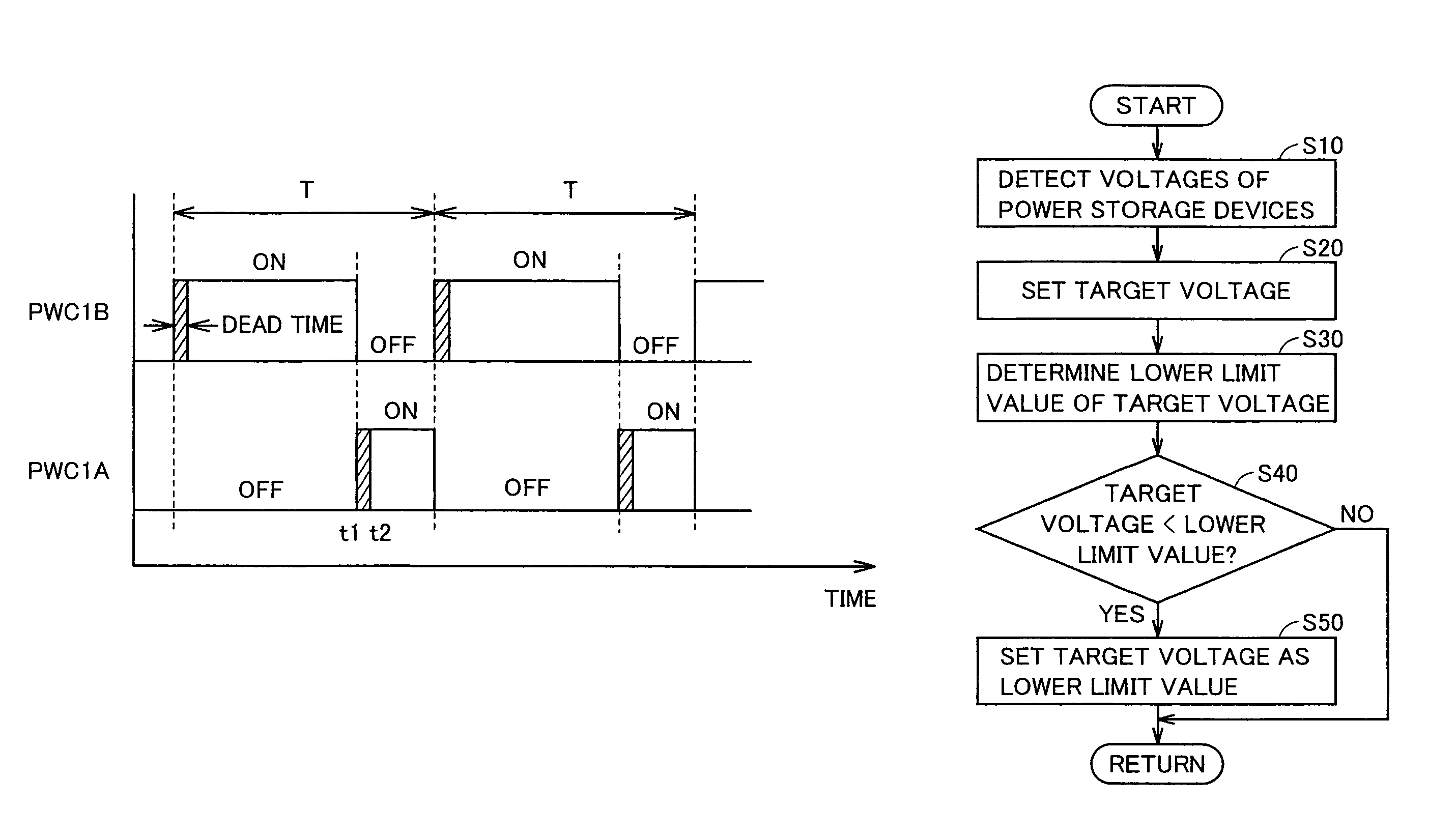
a power supply system and control method technology, applied in the direction of motor/generator/converter stopper, process and machine control, etc., can solve the problems of uncontrollable current flow between the batteries, short circuit between the batteries, etc., to avoid low-boost operation and prevent voltage fluctuations due to the influence of a dead time provided for the converter

Active Publication Date: 2014-08-05
DENSO CORP
View PDF10 Cites 3 Cited by
  • Summary
  • Abstract
  • Description
  • Claims
  • Application Information

AI Technical Summary

Benefits of technology

[0007]Therefore, the present invention has been made to solve such a problem, and one object of the present invention is to prevent voltage fluctuations due to the influence of a dead time provided for converters in a power supply system including a plurality of power storage devices.
[0026]As described above, in the present invention, a plurality of converters are provided corresponding to a plurality of power storage devices, and connected in parallel to a power line. A target voltage lower limit value is provided for a target voltage of the power line, and the target voltage lower limit value is set higher than a maximum one of voltages of the power storage devices. If the target voltage is lower than the target voltage lower limit value, the target voltage lower limit value is set as the target voltage, avoiding low boost operation that causes the target voltage to be substantially identical to the voltages of the power storage devices.
[0027]Therefore, according to the present invention, voltage fluctuations due to the influence of a dead time provided for converters can be prevented.

Problems solved by technology

However, if the buck switch is always kept ON in a configuration including a plurality of power stages as in the power supply control system disclosed in the publication described above, a short circuit occurs between the batteries, and an uncontrollable current flows between the batteries.

Method used


Image

  • Power supply system, vehicle including the same, control method for power supply system, and computer-readable recording medium recording program for causing computer to execute the control method
  • Power supply system, vehicle including the same, control method for power supply system, and computer-readable recording medium recording program for causing computer to execute the control method
  • Power supply system, vehicle including the same, control method for power supply system, and computer-readable recording medium recording program for causing computer to execute the control method

Examples


Embodiment Construction

[0037]Hereinafter, an embodiment of the present invention will be described in detail with reference to the drawings, in which identical or corresponding parts will be designated by the same reference numerals, and the description thereof will not be repeated.

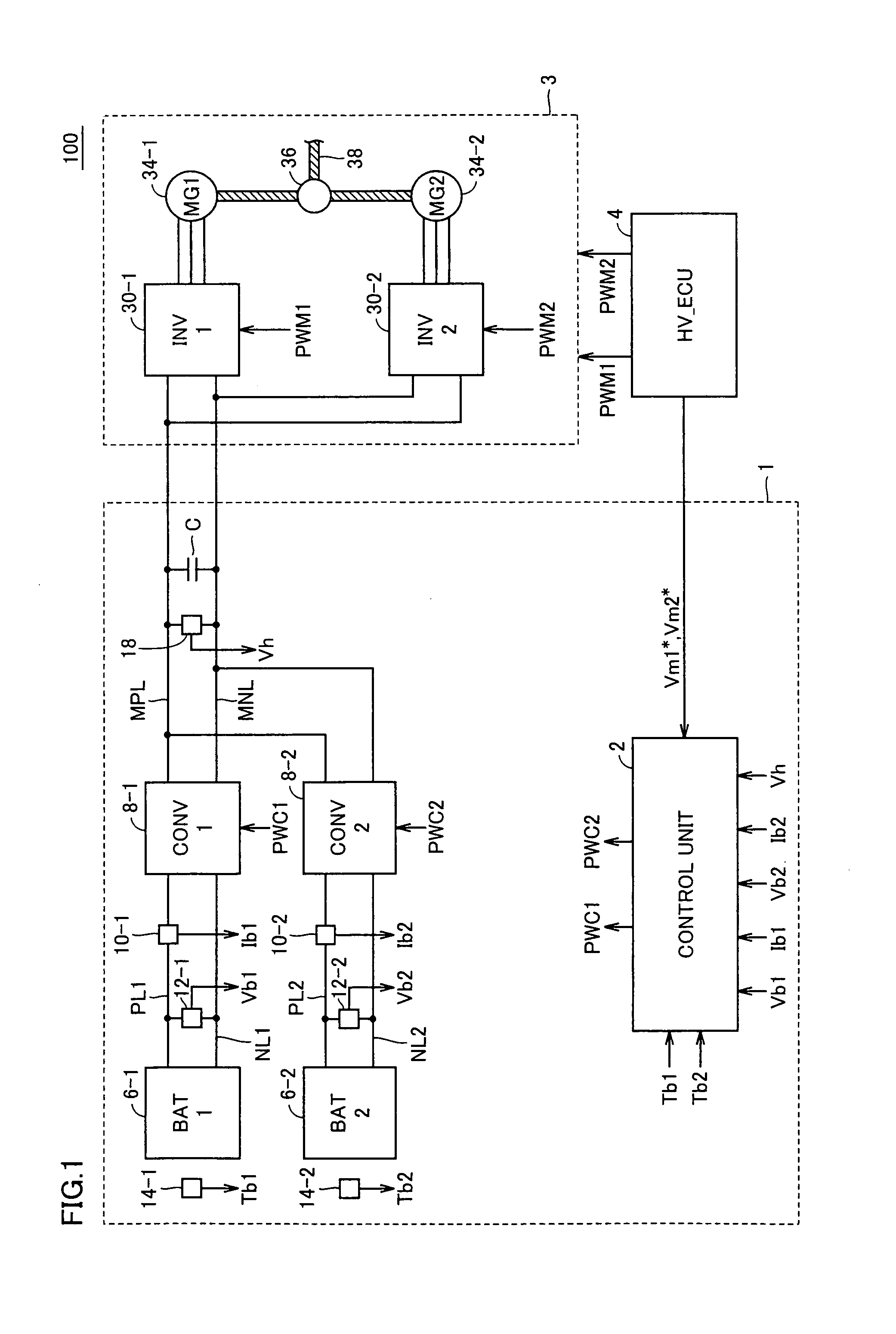
[0038]FIG. 1 is an overall block diagram of a vehicle in accordance with an embodiment of the present invention. Referring to FIG. 1, a vehicle 100 includes a power supply system 1, a drive force generation unit 3, and an HV_ECU (Hybrid Vehicle Electronic Control Unit) 4.

[0039]Drive force generation unit 3 includes inverters 30-1, 30-2, motor-generators 34-1, 34-2, a motive power transfer mechanism 36, and a drive shaft 38. Inverters 30-1, 30-2 are connected in parallel to a main positive bus line MPL and a main negative bus line MNL. Inverters 30-1, 30-2 receive DC power supplied from power supply system 1, and drives motor-generators 34-1, 34-2, respectively. Further, inverters 30-1, 30-2 convert alternate current (AC) power ...


PUM


Abstract

A lower limit value setting unit (52) variably sets a lower limit value (Vth) of a target voltage (Vh*) in a range of a voltage that is higher than the maximum value of voltages (Vb1, Vb2) of power storage devices and is not affected by a dead time provided for converters, based on temperatures (Tb1, Tb2) and required electric powers (Pb1*, Pb2*). A maximum value selection unit (53) sets the maximum value among the voltages (Vb1, Vb2) of the power storage devices and required voltages (Vm1*, Vm2*) of motor-generators, as the target voltage. A target voltage limiting unit (54) compares the target voltage with the lower limit value (Vth), and if the target voltage is lower than the lower limit value (Vth), the target voltage limiting unit (54) sets the lower limit value (Vth) as the target voltage (Vh*).

Description

TECHNICAL FIELD[0001]The present invention relates to a power supply system including a plurality of power storage devices, a vehicle including the same, a control method for a power supply system including a plurality of power storage devices, and a computer-readable recording medium recording a program for causing a computer to execute the control method.BACKGROUND ART[0002]In recent years, in vehicles equipped with electric motors as a motive power source such as hybrid vehicles and electric vehicles, the capacity of a power storage unit has been being increased to improve acceleration performance and running performance such as a maximum traveling distance. As means for increasing the capacity of a power storage unit, a configuration having a plurality of power storage devices has been proposed.[0003]For example, Japanese Patent Laying-Open No. 2003-209969 discloses a power supply control system including a plurality of power stages. The power supply control system includes a pl...

Claims


Application Information

Patent Timeline
Patent Type & Authority Patents(United States)
IPC IPC(8): B60L9/18H02M3/155H02P21/00
CPCB60L11/00Y02T10/70H02J1/102H02M2001/385H02M1/38B60W10/26H02M3/1584B60L50/00H02M1/385
Inventor ICHIKAWA, SHINJI
Owner DENSO CORP
Why Eureka
Try Eureka