Vehicle control apparatus

a technology of vehicle control and control device, which is applied in the direction of hybrid vehicles, engine starters, machines/engines, etc., to achieve the effect of preventing sudden fluctuation in voltage, preventing power increase, and lowering the lower limit of the usable rang

Active Publication Date: 2019-08-20
DENSO CORP
View PDF10 Cites 3 Cited by
  • Summary
  • Abstract
  • Description
  • Claims
  • Application Information

AI Technical Summary

Benefits of technology

[0006]It is an object of the present disclosure to provide a vehicle control apparatus capable of starting an engine by driving a starter even in the event of a trouble with a high-voltage battery in a system that starts the engine by driving the starter with power of the high-voltage battery.
[0008]According to this configuration, the power boost-startup control is executed when it is determined that the high-voltage battery has an abnormality at the time the start request for the engine is made. In the power boost-startup control, the output voltage of the accessory battery is boosted by the DC-DC converter to charge the capacitor with electrical energy by using the power output from the DC-DC converter, so that the engine is started by driving the starter with the electrical energy charged in the capacitor. The engine can thus be started by driving the starter with the power of the accessory battery even when the high-voltage battery has an abnormality.
[0009]In addition, the electrical energy required for starting the engine is temporarily charged in the capacitor so that the starter is driven by the electrical energy charged in the capacitor. With this, it may be possible to prevent a sudden fluctuation in the voltage of the accessory battery and an accompanying adverse effect on the accessory due to the power consumed by the starter while at the same time preventing an increase in power for instantaneous energization of the DC-DC converter. In addition, it may be unnecessary to maintain the state of charge (SOC) of the high-voltage battery higher than or equal to a value required for starting the engine at all times in preparation for a next engine startup, whereby it may be possible to lower the lower limit for the usable range of the SOC of the high-voltage battery.

Problems solved by technology

According to the technique described in Patent Literature 1, the engine may not be started when regenerative power generation cannot be performed while the vehicle is at a standstill at the time of a trouble with the high-voltage battery that is unable to supply enough power therefrom to the MG due to the failure of the high-voltage battery, or when regenerative power generation cannot be performed due to a failure of the MG or an inverter.

Method used


Image

  • Vehicle control apparatus
  • Vehicle control apparatus
  • Vehicle control apparatus

Examples


first embodiment

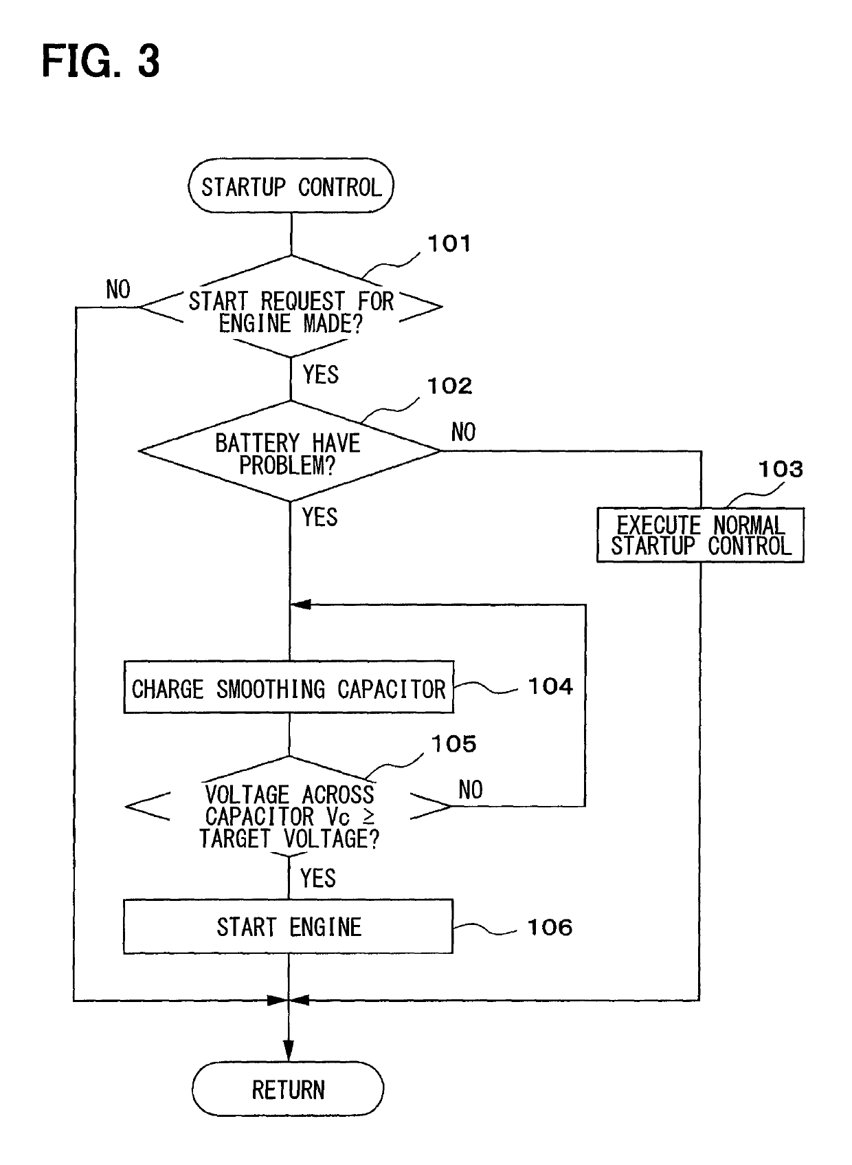
[0021]A first embodiment of the present disclosure will be described with reference to FIG. 1 to FIG. 3.

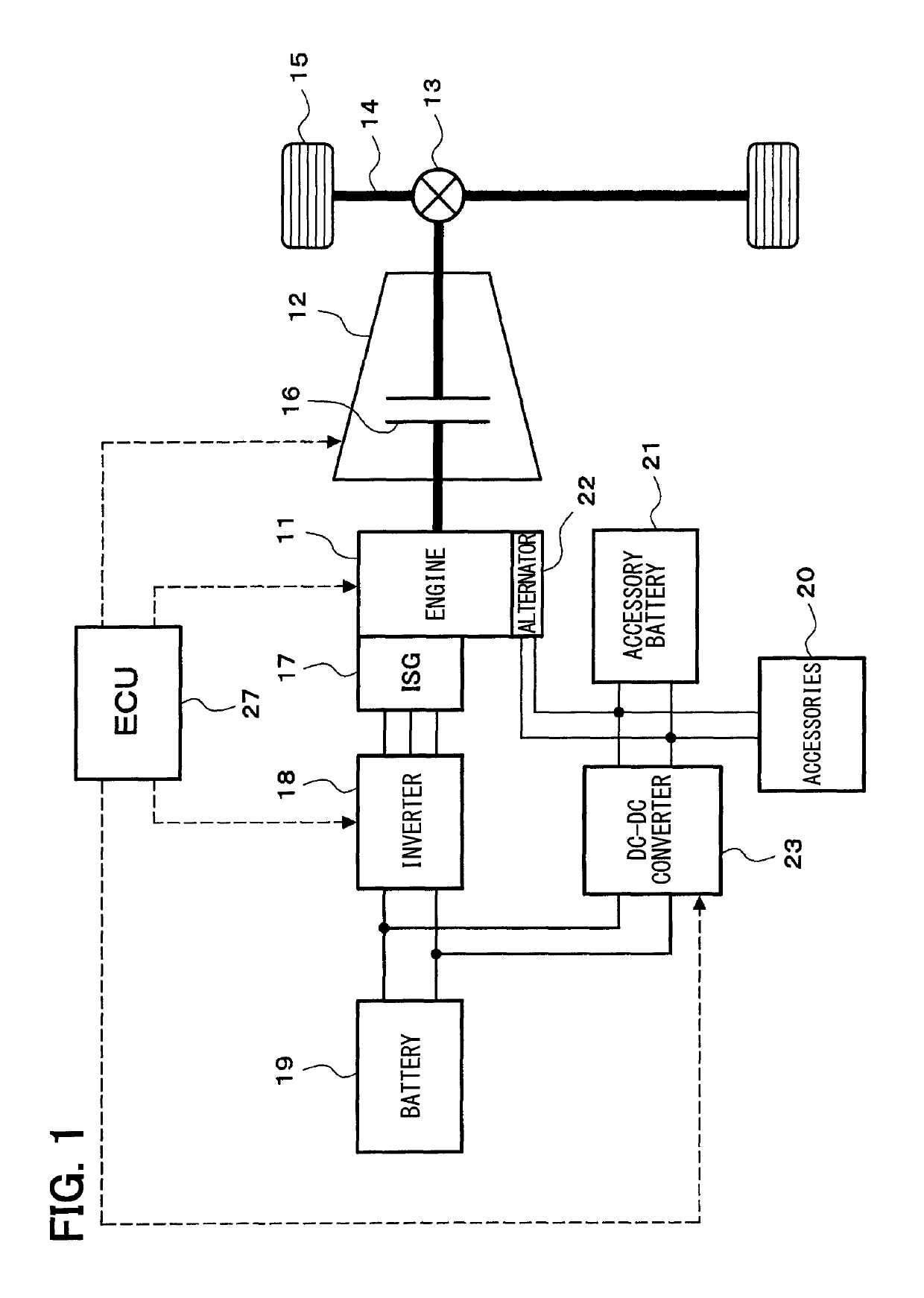
[0022]A schematic configuration of a vehicle drive control system will be described with reference to FIG. 1.

[0023]An engine 11 which is an internal combustion engine is mounted as a power source of a vehicle. Power of an output shaft (a crankshaft) of the engine 11 is transmitted to a transmission 12, and power of an output shaft of the transmission 12 is transmitted to wheels 15 via a differential gear mechanism 13, an axle 14, and the like. The transmission 12 may be a stepped transmission by which a gear position is shifted stepwise from multiple gear positions or a continuously variable transmission (CVT) by which the gear is shifted steplessly. The transmission 12 incorporates a clutch 16 for intermitting power transmission. The clutch 16 may be a hydraulic clutch driven hydraulically or an electromagnetic clutch driven electromagnetically. The clutch 16 may be provided sepa...

second embodiment

[0046]A second embodiment in which the present disclosure is applied to a hybrid vehicle will now be described with reference to FIG. 4 to FIG. 6. Note, however, that a part substantially identical to that of the first embodiment will be denoted by the reference numeral identical to that of the first embodiment and not be described or described in a simplified manner, whereby a part different from the first embodiment will mainly be described.

[0047]In the second embodiment, an engine 11 and a traveling motor generator (MG) 28 are mounted as power sources of a vehicle as illustrated in FIG. 4. Power of an output shaft of the traveling MG 28 is transmitted to wheels 15 via a differential gear mechanism 29, an axle 14, and the like. An MG inverter 30 for driving the traveling MG 28 is connected to a high-voltage battery 19, so that the traveling MG 28 exchanges power with the high-voltage battery 19 via the MG inverter 30.

[0048]As illustrated in FIG. 5, a smoothing capacitor 26 is conn...

third embodiment

[0065]A third embodiment in which the present disclosure is applied to a hybrid vehicle will now be described with reference to FIG. 7 to FIG. 9. Note, however, that a part substantially identical to that of the second embodiment will be denoted by the reference numeral identical to that of the second embodiment and not be described or described in a simplified manner, whereby a part different from the second embodiment will mainly be described.

[0066]In the third embodiment, a boost converter 31 is connected between a high-voltage battery 19 and an MG inverter 30 as illustrated in FIG. 7. The boost converter 31 has a function of boosting a voltage on the side of the high-voltage battery 19 and outputting the voltage to the side of the MG inverter 30, and a function of stepping down a voltage on the side of the MG inverter 30 and outputting the voltage to the side of the high-voltage battery 19.

[0067]As illustrated in FIG. 8, a smoothing capacitor 26 is connected between the boost co...


PUM


Abstract

A vehicle control apparatus comprises an engine, a starter, an accessory battery, and a high-voltage battery. The vehicle control apparatus is equipped with a DC-DC converter that is connected between the accessory battery and the high-voltage battery, a capacitor that is connected to a circuit on a side of the high-voltage battery, a high-voltage battery determination portion, and a startup control portion. The startup control portion executes power boost-startup control, whereby an output voltage of the accessory battery is boosted by the DC-DC converter, the capacitor is charged with necessary electrical energy for starting the engine by using an output voltage of the DC-DC converter, and the starter is driven to start the engine by using the electrical energy charged in the capacitor.

Description

CROSS REFERENCE TO RELATED APPLICATION[0001]This application is based on Japanese Patent Application No. 2015-163980 filed on Aug. 21, 2015, the disclosure of which is incorporated herein by reference.TECHNICAL FIELD[0002]The present disclosure relates to a vehicle control apparatus that starts an engine by driving a starter with power of a high-voltage battery.BACKGROUND ART[0003]In recent years, a hybrid vehicle equipped with an engine and a motor generator (MG) as power sources of a vehicle has attracted attention due to societal demands for fuel-efficient, low-emission vehicles. An example of such a hybrid vehicle is described in Patent Literature 1. The hybrid vehicle described in the literature uses an MG connected to a high-voltage battery (a power storage device) as a starter, and cranks and starts an engine by driving the MG with power of the high-voltage battery. When enough power cannot be supplied from the high-voltage battery to the MG due to a failure of the high-volta...

Claims


Application Information

Patent Timeline
Patent Type & Authority Patents(United States)
IPC IPC(8): F02N11/08F02N11/04F02D29/02B60W10/26B60W10/08B60W10/06B60W10/00B60K6/547B60K6/543B60K6/485B60K6/442B60K6/28B60W20/50F02D29/06
CPCF02N11/0844B60K6/442B60K6/485B60K6/543B60K6/547B60W10/00B60W10/06B60W10/08B60W10/26F02N11/04F02N11/08B60K6/28Y02T10/6286B60W20/50F02D29/02F02D29/06Y02T10/6226Y02T10/6234F02N11/0866F02N11/108F02N2011/0888F02N2011/0896B60W20/40Y02T10/62
Inventor KOBAYASHI, HISAAKI
Owner DENSO CORP
Why Eureka
Try Eureka