Sensory signal output apparatus and the ouput compensation method using electromagnetic field

A technology of induction signal and output equipment, applied in the field of induction signal output equipment, can solve the problems of reducing production efficiency, large vibration force difference, increasing production cost, etc., and achieve the effect of improving production efficiency, reducing product cost and improving product quality

Inactive Publication Date: 2010-08-18
BUJEON
View PDF0 Cites 2 Cited by
  • Summary
  • Abstract
  • Description
  • Claims
  • Application Information

AI Technical Summary

Problems solved by technology

[0009] If the above-mentioned resonance point error occurs, it will be treated as an unqualified characteristic according to the degree of error. Therefore, if an error occurs in the finished product state, it can only be treated as a non-conforming product.
In addition, even if it is a qualified product, there will be a large difference in vibration force at a single frequency due to the difference of 1~2Hz. Therefore, the benchmark tolerance range of the product performance index must be set larger, and for installation and use users of the product, it is necessary to take these deviations into consideration before using the
[0010] As mentioned above, in the past, when a defect occurred in the finished product state, since the characteristic correction could not be performed, the finished product could only be scrapped, so not only the production efficiency was reduced, but also the production cost was increased.
In addition, even for qualified products, there are large deviations between products

Method used


Image

  • Sensory signal output apparatus and the ouput compensation method using electromagnetic field
  • Sensory signal output apparatus and the ouput compensation method using electromagnetic field
  • Sensory signal output apparatus and the ouput compensation method using electromagnetic field

Examples


Embodiment Construction

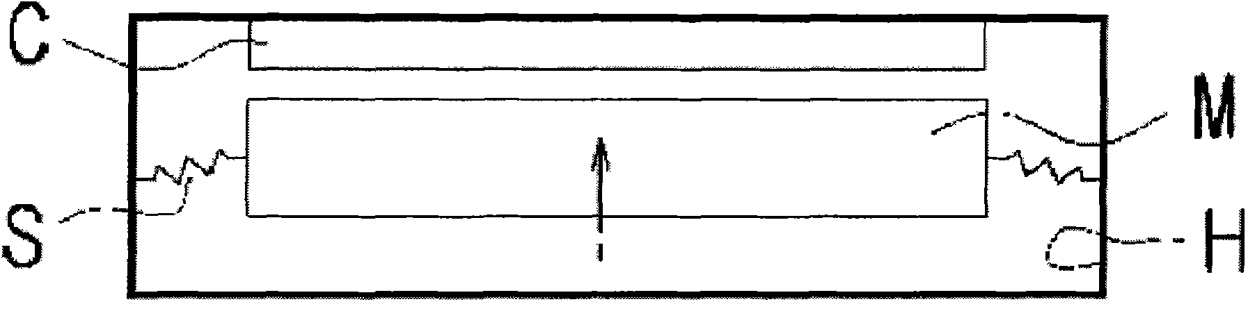
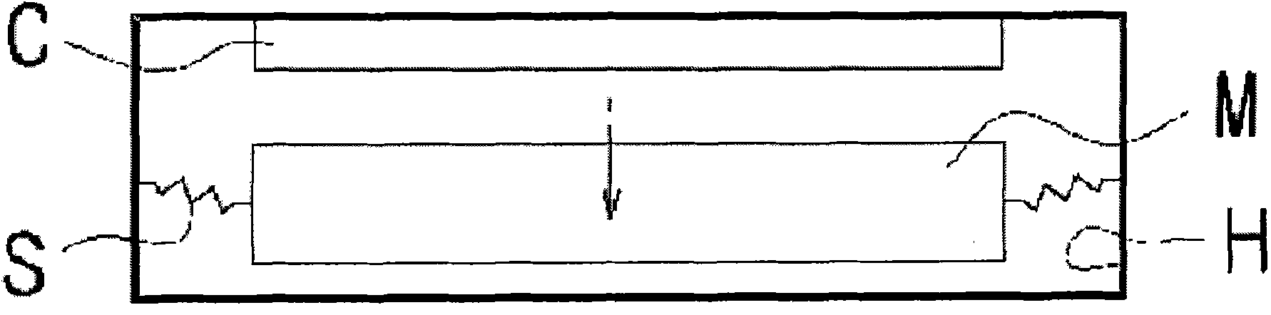
[0028] Before describing the present invention, each drawing will be briefly described. Figure 4 is a sectional view showing the structure of an embodiment of the present invention, Figure 5 is a sectional view showing another structure of an embodiment of the present invention, Image 6 It is a sectional view showing yet another structure of an embodiment of the present invention, Figure 7 It is a sectional view showing yet another structure of an embodiment of the present invention, Figure 8 It is a sectional view showing the structure of a more detailed embodiment of the present invention, Figure 9 to Figure 15 It is a cross-sectional view showing the structure of another embodiment of the present invention in more detail, Figure 16 , Figure 17 It is a cross-sectional view showing the mechanical working state of the present invention, Figure 18 is an experimental result table showing experimental data (diameter change) of the present invention, Figure 19 is a...


PUM


Abstract

The present invention relates to a sensory signal output device using an electromagnetic field and a method for correcting a characteristic error thereof. A sensory signal output device (10) using an electromagnetic field, outputting a sensory signal through the vibration of a magnetic circuit (2) responding to the electromagnetic field, includes: an attraction means (11) that mutually interacts with the magnetic circuit (2), changing resonant frequency, and changing gravity in single frequency when the magnetic circuit (2) received in a case (1) approaches the attraction means (11) which is vibrating. The present invention controls a resonant frequency point in finished or half-finished products by artificially changing the gravity through simply mounting and unmounting of the attraction means (including exchange), easily correcting an error in output characteristics. Furthermore, the present invention remarkably reduces the error rate in finished products by correcting an error of output characteristics, improving productivity as well as reducing production costs. Furthermore, the present invention maintains optimum performance and reduces performance deviation in products.

Description

technical field [0001] The present invention relates to an induction signal output device using an electromagnetic field that outputs vibration or sound or simultaneously outputs vibration and sound through the vibration of a magnetic circuit interacting with an alternating electric field. Background technique [0002] Generally speaking, the inductive signal output device is a loudspeaker, receiver, buzzer, vibrating body (oscillator (including vibrating motor)) that converts the electrical signal input by the signal source into a mechanical signal, thereby outputting sound or generating vibration ) and other sound or vibration force output equipment collectively. [0003] In the past, the induction signal output equipment such as figure 1 , figure 2 As shown, the magnetic circuit M vibrates with the change of the electric field of the coil C, that is, the magnetic circuit M supported by the elastic support S vibrates in the up and down direction, outputting vibration fo...

Claims


Application Information

Patent Timeline
Patent Type & Authority Applications(China)
IPC IPC(8): H02K33/18
CPCH02K33/16H04R2400/07H04R2400/03H02K33/02H04R1/20H04R7/00
Inventor 姜允圭舶贤哲
Owner BUJEON
Why Eureka
Try Eureka