
Power tool

A technology of electric tools and electric current, which is applied in the direction of motor tools, manufacturing tools, striking tools, etc., can solve the problem of reducing operating force, and achieve the effect of reducing component load and operating force

Active Publication Date: 2010-08-25
ROBERT BOSCH GMBH
View PDF14 Cites 10 Cited by
  • Summary
  • Abstract
  • Description
  • Claims
  • Application Information

AI Technical Summary

Problems solved by technology

In this way, it can also be possible to change the operating state within unsuitable parameter ranges without causing damage to the component by the operator, or to reduce the actuating force for changing into the new operating state.

Method used

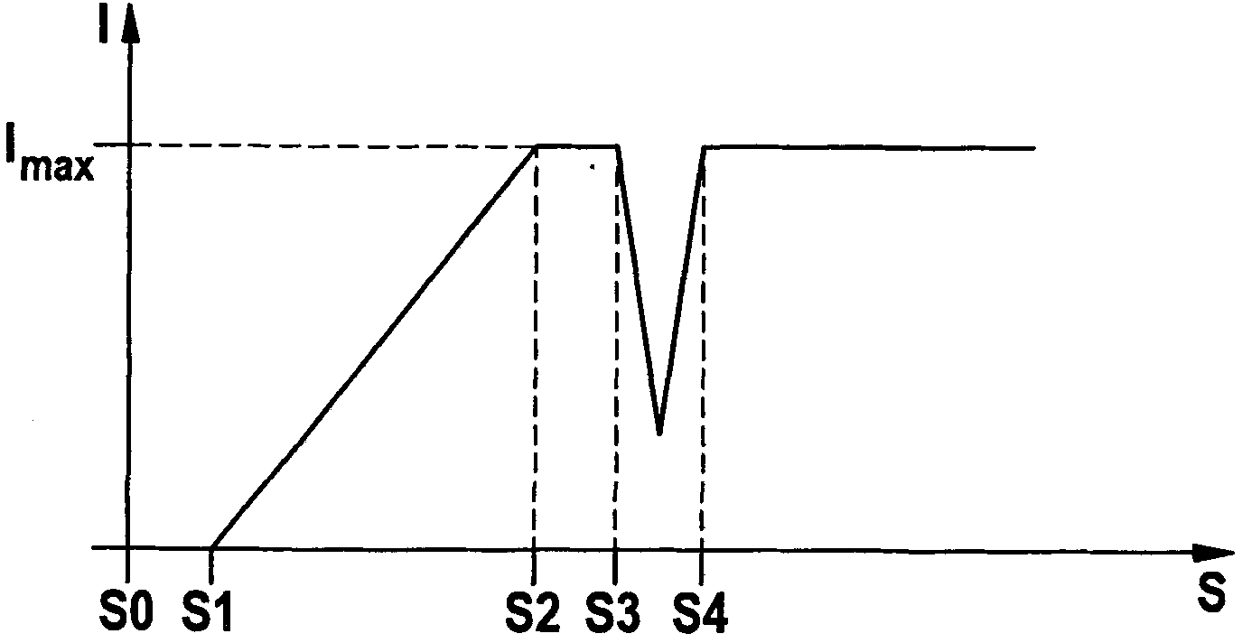

Image

  • Power tool
  • Power tool
  • Power tool

Examples


Embodiment Construction

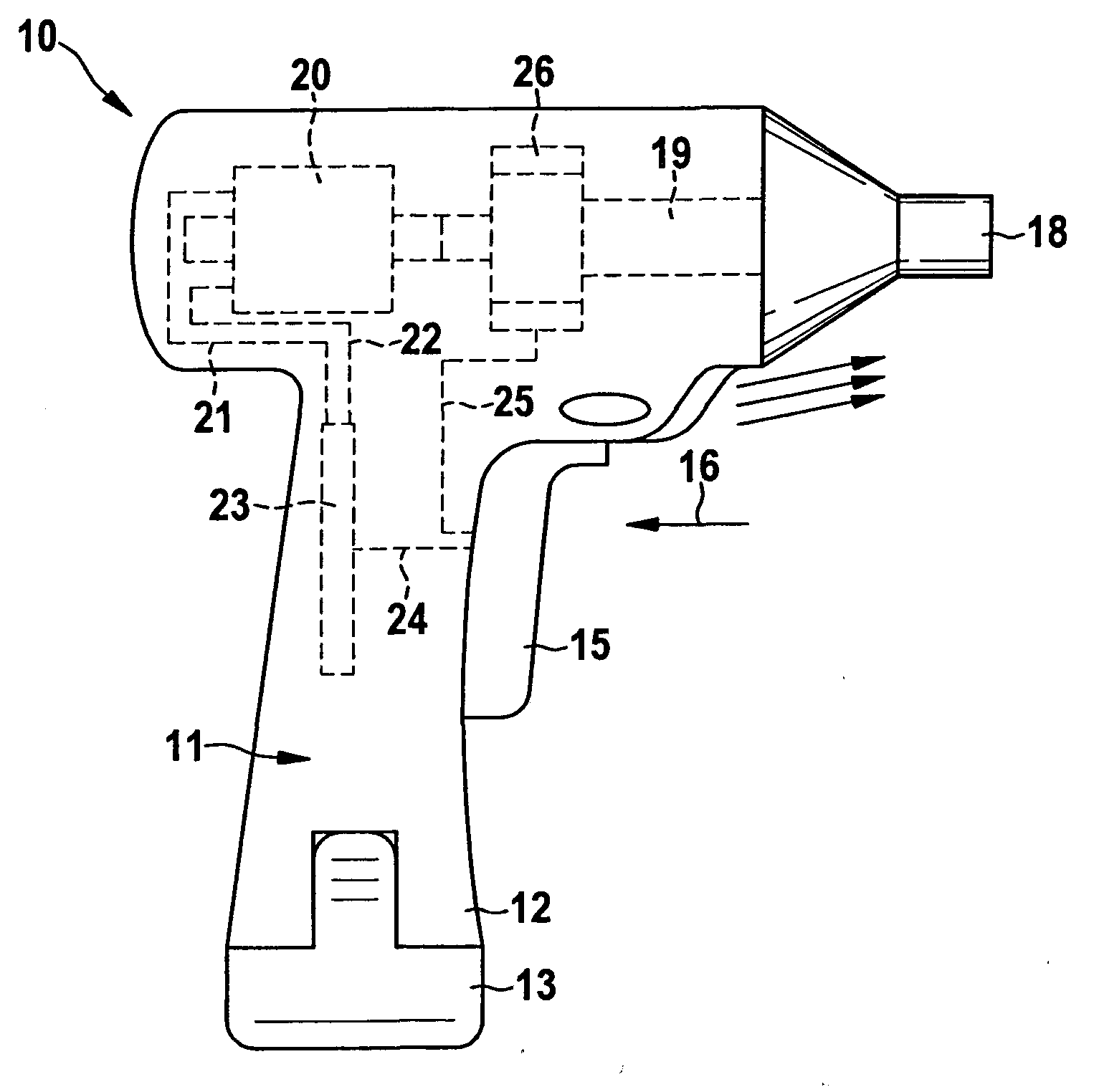
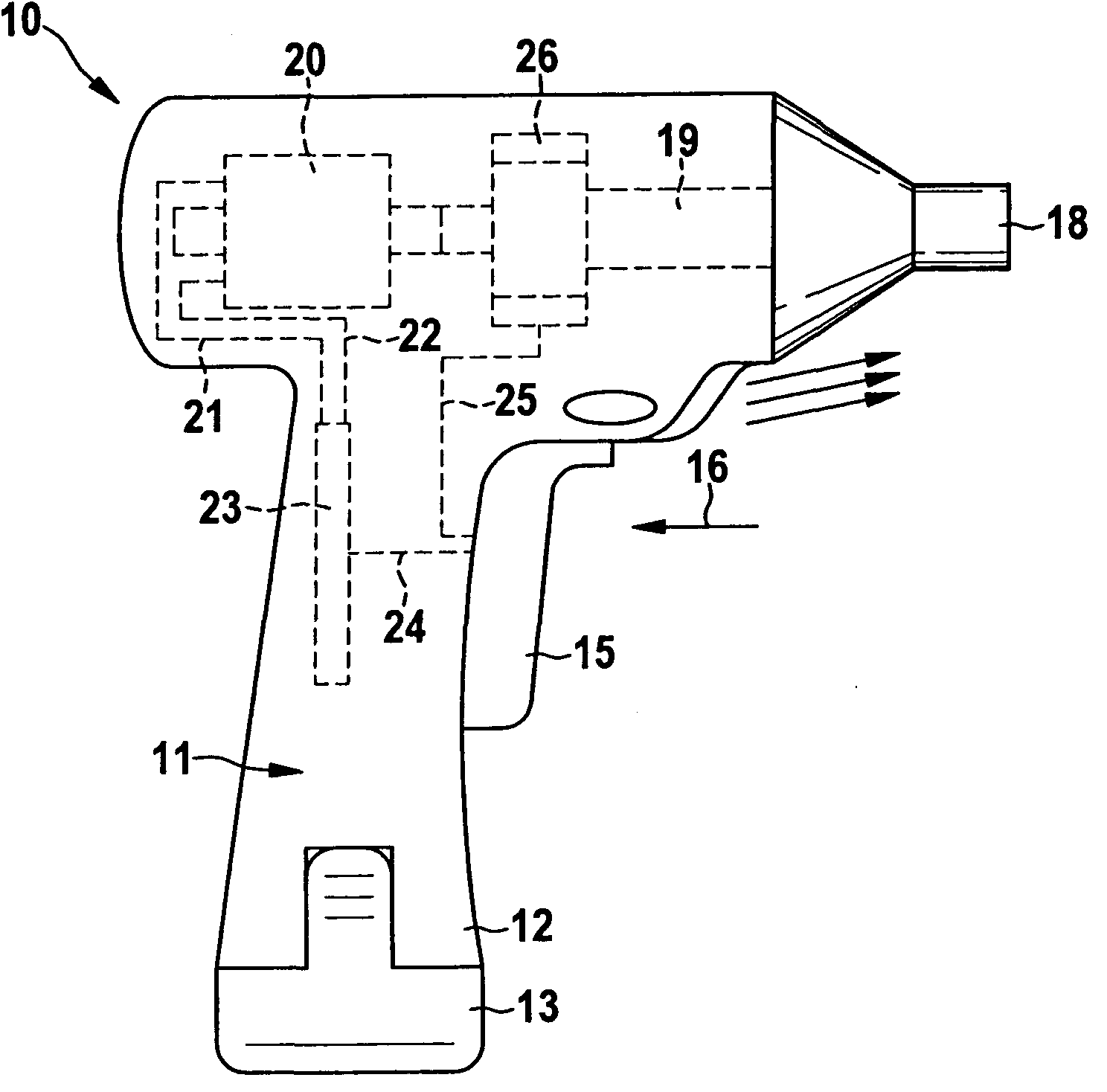
[0019] FIG. 1 shows a hand drill 10 which has a housing 11 . It can also be seen that at the lower end of the handle 12 there is a battery pack 13 which is used as an energy source for the drive (motor) of the hand drill 10 and for the electronics. Also mounted on the handle 12 is a switching pawl 15 which can be moved by the operator in the direction of the arrow 16 . Furthermore, the movement of the switching pawl 15 in the direction of the arrow 16 is also denoted as the movement path S of the switching pawl 15 .

[0020] The hand drill 10 internally has a drive motor 20 which is coupled via a transmission to the drill holder 18 or the spindle. The driving motor 20 is connected to the power control switch 23 through the lines 21 and 22 , and the power control switch 23 is connected to the switch pawl 15 through the line 24 or controlled and activated by the switch pawl 15 .

[0021] The switching pawl 15 is additionally connected via a connecting device 25 to an automatic...


PUM


Abstract

The electric tool (10, 10a) includes a drive motor (20, 20a) and at least one additional device (26, 26a) coupled to the drive motor (20, 20a) for changing between at least two different operating states. The drive motor (20, 20a) and the additional device (26, 26a) are controllable by means of at least one operating device (15, 15a, 30). The power of the drive motor (20, 20a) is changed on activation of the at least one additional device (26, 26a). This results in a reduction of the operating forces on changing between operating states and a reduction of the component loading.

Description

technical field [0001] The invention relates to an electric tool according to the preamble of claim 1 . Background technique [0002] US Pat. No. 6,800,045 B1 discloses a power tool in the form of a drill, according to the preamble of claim 1 , the transmission of which is connected to the drive motor and is connected to an additional gear. This additional gearing automatically matches the gear ratio during operation to the load demand. This means, for example, that the rotational speed of the transmission during drilling decreases as the hardness of the material to be drilled increases. This is achieved by means of known additional gearing without the drive having to be stopped for this purpose. [0003] It is also known from JP 7308813 A to provide a shifting device on the vertical drilling machine, which enables quick shifting during operation. No other characteristics can be derived from this document, especially with regard to possible speed control during gear chang...

Claims


Application Information

Patent Timeline
Patent Type & Authority Applications(China)
IPC IPC(8): B25F5/00B25D16/00B23B45/02B23B47/04B23Q5/12
CPCB25D16/006B25B21/008B25D2250/205B25D2250/221B23B45/008B25F5/001
Inventor T·齐默尔曼H·勒姆J·韦尔克D·绍尔
Owner ROBERT BOSCH GMBH
Learn More