Underwater side-scan sonar collecting and releasing device arranged under boat bow deck
A side-scan sonar, retractable device technology, which is applied to measurement devices, ships, navigation aid arrangements, etc., can solve the problems of unsatisfactory acoustic imaging quality, poor rigidity, and long retractable and retractable rods, and achieves good rigidity and ease of use. Convenient, safe and fast retractable effect
- Summary
- Abstract
- Description
- Claims
- Application Information
AI Technical Summary
Problems solved by technology
Method used
Image
Examples
Embodiment 1
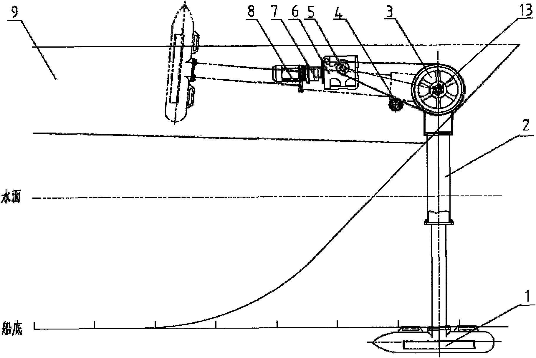
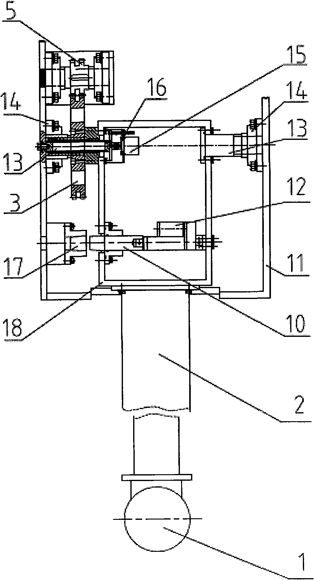
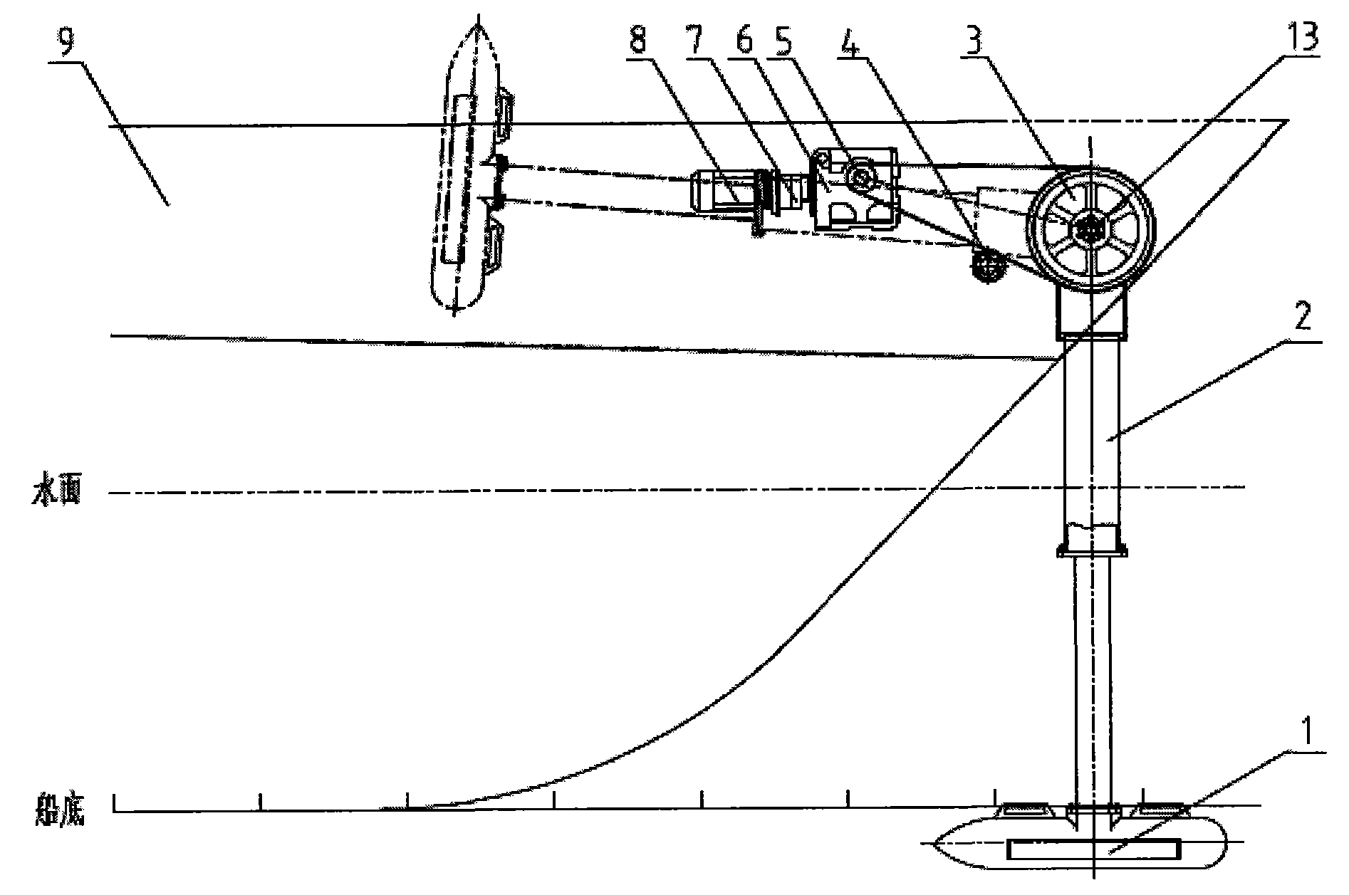
[0025] Embodiment one: see figure 1 and figure 2 , the underwater side-scanning sonar retractable device installed under the bow deck, including the bow storage tank 9, sonar 1, encoder 15, is characterized in that the sonar 1 is installed in a swing retractable mechanism Above, the swing retractable mechanism is installed in the bow storage groove 9, and the swing of the swing retractable mechanism enables the sonar 1 to be stored in the bow storage groove 9 or placed in the bow storage groove 9. In the down position: the encoder 15 is installed in the rod end frame 18 of the swing retractable mechanism, connected with the rotating shaft 13 through a coupling 16, and feeds back the retractable angle of the sonar 1 .
Embodiment 2
[0026] Embodiment 2: This embodiment is the same as Embodiment 1, and the special features are as follows: the structure of the swing retractable mechanism is: one end of a retractable rod 2 is fixedly installed with the sonar 1, and the other end is connected with a rotating shaft 13 is fixed, the two ends of the rotating shaft 13 are supported on the hull steel plates 11 on both sides of the bow receiving groove 9 through flange bearings 14, a large sprocket 3 is fixedly installed on the rotating shaft 13, and a motor 8 is fixedly installed On the hull steel plate 11, the motor 8 drives a small sprocket 5 through a gear reducer 7 and a worm gear reducer 6, and the small sprocket 5 drives the large sprocket 3 through a stainless steel chain.
[0027] The fixed connection structure between one end of the retractable rod 2 and the rotating shaft 13 is: the end of the retractable rod 2 is fixedly connected to a rod end frame 18, and the rotating shaft 13 is a short shaft separate...
Embodiment 3
[0031] Embodiment 3: The underwater side-scanning sonar 1 is installed on the bow of the boat, and its working position is perpendicular to the bottom of the boat and in the same plane as the bottom of the boat. like figure 1 shown. When receiving, the sonar is placed in the receiving groove 9. When the sonar is in this position, the top cover can be closed to protect the sonar. The retractable rod 2 adopts a two-stage hollow method to reduce dead weight and improve rigidity. Sonar is installed on retractable rod 2 one ends. Retractable rod 2 other ends install rotating shaft 13, and rotating shaft is fixed with hull by flange bearing 14. When the sonar is ready to work from the storage position, the sonar is rotated to the bow working position perpendicular to the bottom of the ship through the motor 8, the gear reducer 7, the worm gear reducer 6, the small sprocket 5, the stainless steel chain, and the large sprocket 3 . When the working position is reached, the positi...
PUM
 Abstract
Description
Claims
Application Information
 - R&D
- Intellectual Property
- Life Sciences
- Materials
- Tech Scout
- Unparalleled Data Quality
- Higher Quality Content
- 60% Fewer Hallucinations
Browse by: Latest US Patents, China's latest patents, Technical Efficacy Thesaurus, Application Domain, Technology Topic, Popular Technical Reports.
© 2025 PatSnap. All rights reserved.Legal|Privacy policy|Modern Slavery Act Transparency Statement|Sitemap|About US| Contact US: help@patsnap.com


