Furnace cap water-cooling device for converter

A water-cooling device and furnace cap technology, which is applied in the field of converter furnace cap water-cooling devices and water-cooling devices, can solve problems such as uneven distribution of angle steel, long water temperature, and poor cooling effect

Inactive Publication Date: 2012-01-11
SHANGHAI MEISHAN IRON & STEEL CO LTD
View PDF0 Cites 0 Cited by
  • Summary
  • Abstract
  • Description
  • Claims
  • Application Information

AI Technical Summary

Problems solved by technology

[0003] As far as the applicant knows, there are roughly two types of water cooling devices installed on the converter cap at present. One is to install two rings of steel pipes on the furnace cap, and then use multiple angle steels to communicate between the two rings of steel pipes. The disadvantage of this structure is : The arrangement of angle steel is uneven and the water circulation is not smooth, resulting in poor cooling effect; the other is to set up multiple circles of steel pipes on the upper and lower sides of the furnace cap and each steel pipe is provided with water inlet and outlet separately. The disadvantage of this structure is that the cooling water needs to be Make a circle around the furnace cap in the steel pipe, the flow path is too long so that the water temperature in the steel pipe is too high; and in order to leave a gap for installing the slag retaining skirt support plate, the steel pipes should not be too closely spaced, thereby reducing the cooling effect

Method used


Image

  • Furnace cap water-cooling device for converter
  • Furnace cap water-cooling device for converter
  • Furnace cap water-cooling device for converter

Examples


Embodiment

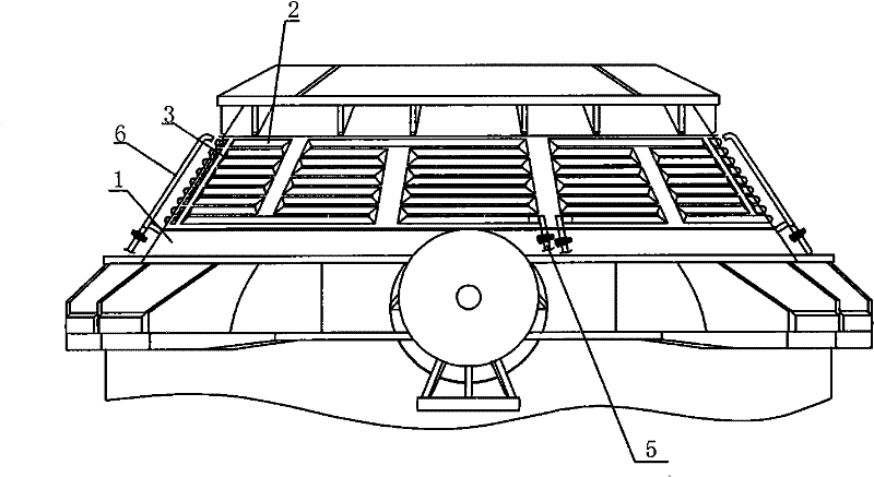
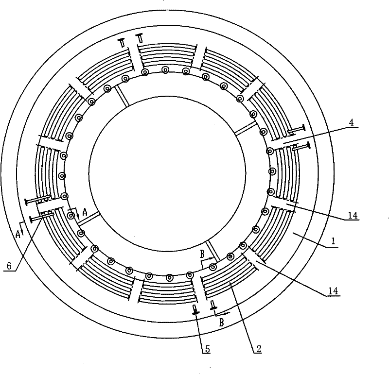
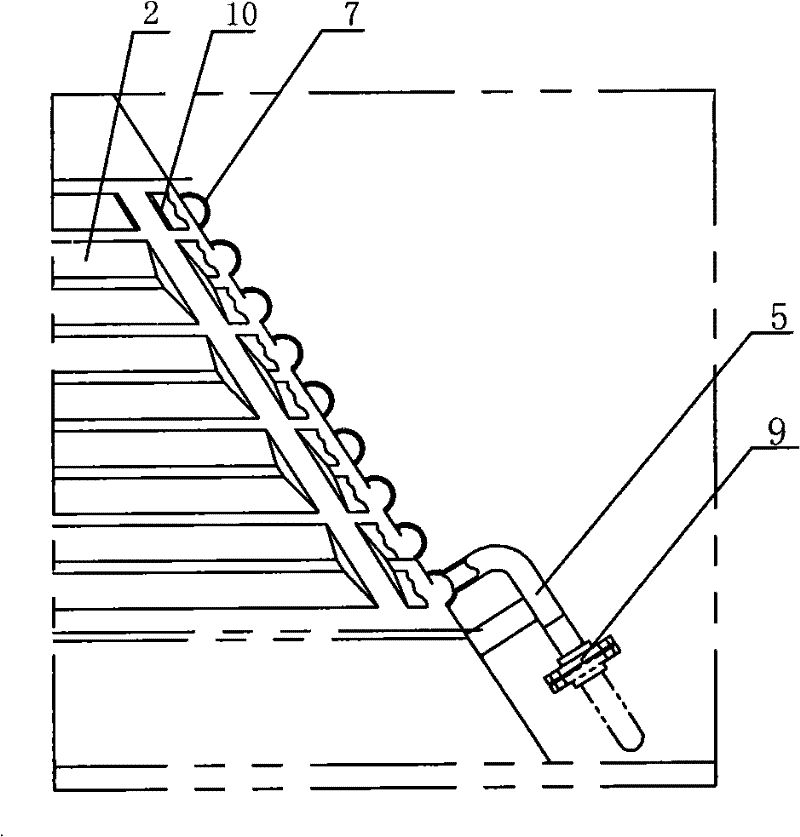
[0016] The converter cap water cooling device of the present embodiment is as figure 1 with figure 2 As shown, it includes a steel pipe placed on the outer surface of the furnace cap 1, and the steel pipe is divided into four sections along the circumference of the furnace cap 1. Between each section of steel pipes and in each section of steel pipes, there is a gap for installing the slag retaining skirt support plate, and the gap includes a first gap 4 between each section of steel pipes and two first gaps 4 in each section of steel pipes The second neutral gear is 14, and the total number of neutral gears is 12. Each section of steel pipe is composed of horizontal steel pipes 2 welded on the outer surface of furnace cap 1 at intervals up and down and vertical steel pipes 3 connected to the same end of adjacent horizontal steel pipes 2 . The horizontal steel pipes 2 alternately communicate with each other between the uppermost end and the lowermost end of the two second ga...


PUM


Abstract

The invention relates to a furnace cap water-cooling device for a converter and belongs to the technical field of auxiliary devices of a converter. The furnace cap water-cooling device for the converter comprises a steel tube arranged on the outer surface of the furnace cap; the steel tube is divided into at least three sections along the circumference of the furnace cap; the sections of the steel tube are arranged in a snake shape at intervals along the outer surface of the furnace cap and are provided with a gap for accommodating a slag-blocking skirt support plate respectively; and head and tail ends of each section of the steel tube are connected with a water inlet pipe and a water outlet pipe respectively. The cooling water in each section of the steel tube of the furnace cap water-cooling device for the converter only densely flows through a smaller region of the outer surface of the furnace cap, so that the circulation of the cooling water is accelerated, the area covering the outer surface of the furnace cap is increased, and the water temperature is reduced. Therefore, the cooling effect of the furnace cap is greatly improved.

Description

technical field [0001] The invention relates to a water cooling device, in particular to a water cooling device for a converter cap, and belongs to the technical field of converter auxiliary devices. Background technique [0002] The furnace cap of the converter is mainly used to reduce the loss of slag splashing and heat loss in the furnace during blowing, so it always works at a high temperature. In order to prevent the furnace cap from being damaged in a long-term high temperature state and prolong its service life, the existing converter furnace cap is equipped with a cooling device, and usually a water cooling device is used. [0003] As far as the applicant knows, there are roughly two types of water cooling devices installed on the converter cap at present. One is to install two rings of steel pipes on the furnace cap, and then use multiple angle steels to communicate between the two rings of steel pipes. The disadvantage of this structure is : The arrangement of ang...

Claims


Application Information

Patent Timeline
Patent Type & Authority Patents(China)
IPC IPC(8): C21C5/46
CPCY02P10/20
Inventor 施卫忠牟世学陈德亮朱立江张国日黄超常发
Owner SHANGHAI MEISHAN IRON & STEEL CO LTD
Why Eureka
Try Eureka